Control device for internal combustion engine

a control device and internal combustion engine technology, applied in the direction of electrical control, process and machine control, etc., can solve the problems of driving torque deviating from the target value, vehicle behavior intended by the driver not being implemented, etc., to improve the control response characteristic and control stability in driving force control in the vehicl

Inactive Publication Date: 2009-02-05
TOYOTA JIDOSHA KK
View PDF11 Cites 45 Cited by
  • Summary
  • Abstract
  • Description
  • Claims
  • Application Information

AI Technical Summary

Benefits of technology

[0010]The present invention was made to solve the above-described problems. An object of the present invention is to provide a driving force control device for a vehicle (a control

Problems solved by technology

Under acceleration/deceleration (transient response), however, not only inertia torque relevant to a change of the gear ratio of the automatic transmission with respect to time but also inertia torque relevant to a change of a wheel speed with respect to time causes the driving torque to deviate from the target value.
Further, in the case where how the gear ratio should be changed is determined based on a transmission map using a throttle position and a vehicle speed, the following problems arise.
In th

Method used


Image

  • Control device for internal combustion engine
  • Control device for internal combustion engine
  • Control device for internal combustion engine

Examples


first embodiment

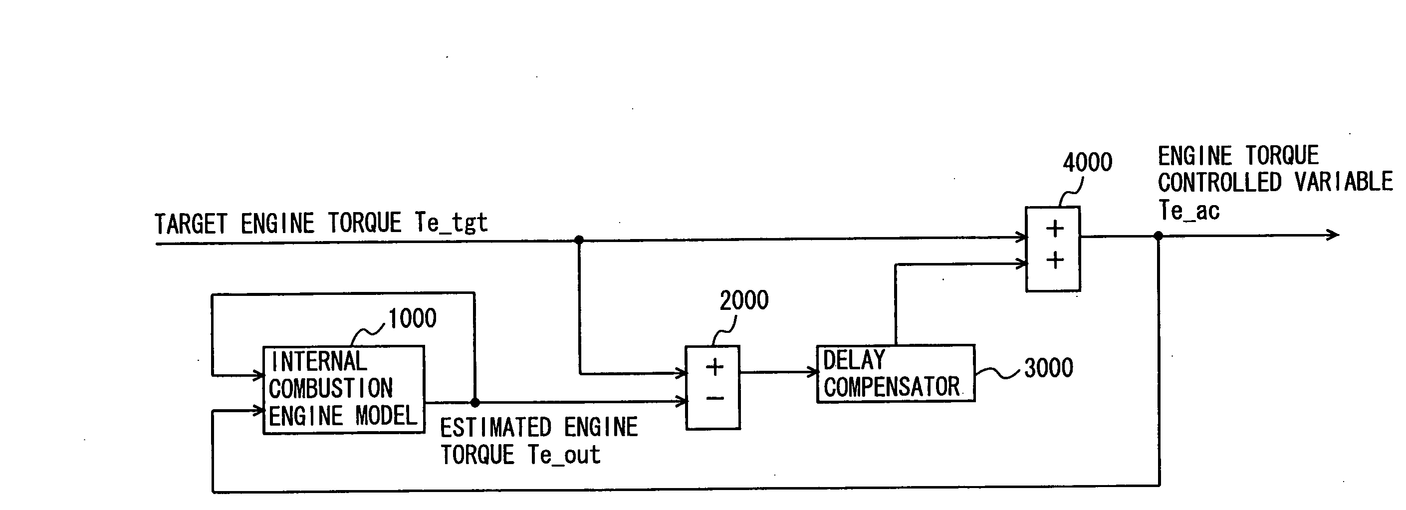
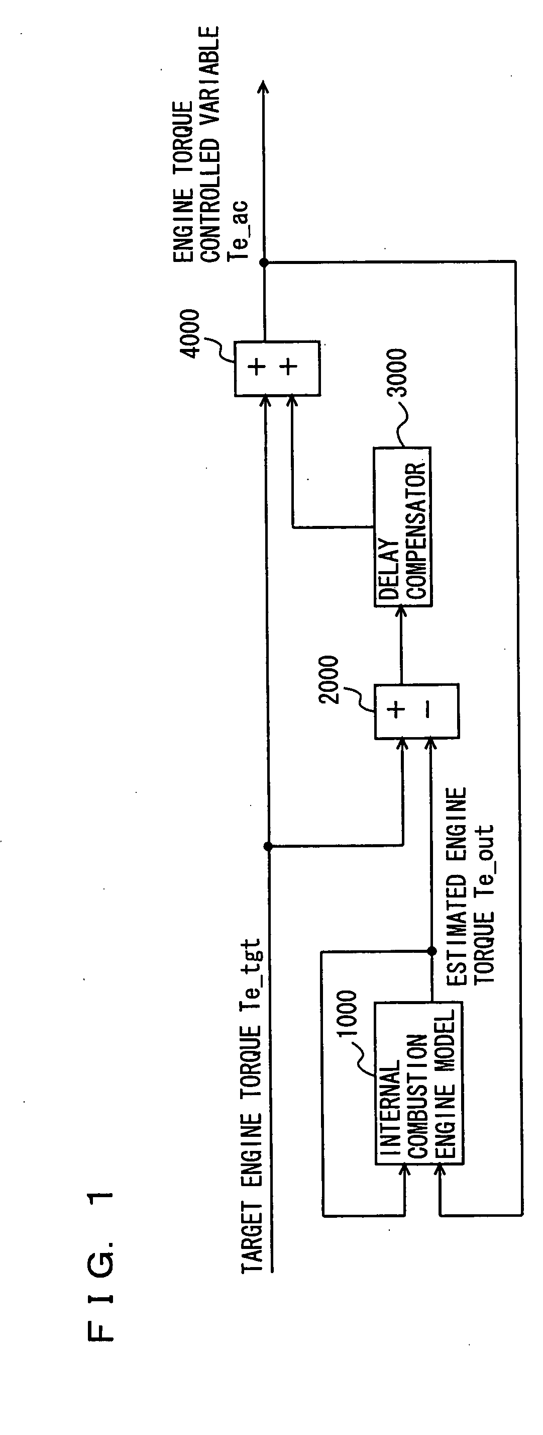
[0041]The driving force control system according to the present embodiment aims to improve the response characteristic. In calculating an engine torque controlled variable for implementing target engine torque, the driving force control system calculates the target engine torque by compensating for response delay in control with respect to a difference between the estimated engine torque estimated from the target engine torque controlled variable and the target engine torque. Thus, the controlled variable for which response delay in control has accurately been compensated for can be calculated. Here, an internal combustion engine model used for calculating the estimated engine torque is assumed as a linear model without including a dead time, so that implementation on an ECU (Electronic Control Unit) is facilitated.

[0042]A control block diagram of the driving force control system according to the present embodiment will be described with reference to FIG. 1. It is noted that a trans...

second embodiment

[0059]A driving force control system according to the second embodiment of the present invention will be described hereinafter. The driving force control system according to the present embodiment aims to avoid occurrence of overshoot due to a dead time in the internal combustion engine. In the driving force control system according to the first embodiment described above, as the transfer function for the internal combustion engine includes the dead time component, the transfer function for the internal combustion engine at the time point of calculation of the engine torque controlled variable and the transfer function when the torque controlled variable is implemented are different from each other, and overshoot such as overflow and underflow occurs. Consequently, a behavior of the vehicle is disturbed.

[0060]Therefore, in the driving force control system according to the present embodiment, taking into consideration the dead time in the internal combustion engine, the transfer func...

third embodiment

[0088]In the embodiments described above, delay compensation, or dead time compensation in addition to delay compensation is performed. Namely, such compensation is made (compensation is made to raise a controlled variable by multiplying deviation between an estimated actual output value and a target value by gain, allowing for delay and dead time). If such compensation is unexceptionally made for slight variation in the target value, hunting of an actuator (such as an electronic throttle valve adjusting an intake air amount) occurs and durability may be lowered. In particular, even when feedback control is being carried out and a stable state is attained (basically when there is no change in driving force requested by a driver or a vehicle control system (such as cruise control)), the target value calculated through operation is constantly varied. Normally, such fluctuation is minor and response characteristic thereto does not give rise to a problem. Therefore, in the present embod...


PUM


Abstract

A driving force control system includes an internal combustion engine model (1000) represented by a model linearized while including a first-order lag component, a calculator (2000) calculating deviation between target engine torque and estimated engine torque, a delay compensator (3000) compensating for response delay based on the deviation, and an adder (4000) calculating an engine controlled variable by adding delay-compensated deviation to the target engine torque.

Description

TECHNICAL FIELD[0001]The present invention relates to a control device for a vehicle including a powertrain having an engine and a transmission, and more particularly to a driving force control device (a control device for an internal combustion engine) capable of outputting driving force corresponding to driving force requested by a driver while realizing excellent control response characteristic and control stability.BACKGROUND ART[0002]With regard to a vehicle including an engine and an automatic transmission capable of controlling engine output torque independently of accelerator pedal operation by a driver, there is a concept of “driving force control” that positive and negative target drive torque calculated based on a degree of pressing the accelerator pedal by a driver, a vehicle operation condition and the like is achieved as engine torque and a gear ratio of the automatic transmission. Control schemes referred to as “driving force request type” and “driving force demand ty...

Claims


Application Information

Patent Timeline
IPC IPC(8): G06F19/00F02D41/04F02D45/00
CPCF02D41/1401F02D41/1497F02D2041/1429F02D2250/18F02D2041/1433F02D2200/1004F02D2041/1431
Inventor KUWAHARA, SEIJIKAIGAWA, MASATO
Owner TOYOTA JIDOSHA KK
Why Eureka
Try Eureka