Steering System

a steering system and steering wheel technology, applied in the direction of fluid steering, hydraulic steering gears, vehicle components, etc., can solve the problems of mounting and preservation of vehicle cabin space, difficult to suppress by design or control measures, and cable is expected to be difficult to handl

Inactive Publication Date: 2009-02-12
HITACHI LTD
View PDF2 Cites 22 Cited by
  • Summary
  • Abstract
  • Description
  • Claims
  • Application Information

AI Technical Summary

Benefits of technology

[0016]Accordingly, the object of the present invention is to provide a steering system, in which the set of the ratio of the steered angle of the wheel tire to the steering angle of the steering wheel can be changed depending on the driving situation without causing any sensation of discomfort to the driver.
[0053]The present invention enables to provide a steering system, in which the set of the ratio of the steered angle of the wheel tire to the steering angle of the steering wheel can be changed depending on the driving situation without causing any sensation of discomfort to the driver.

Problems solved by technology

Although the technology described in the above-mentioned Japanese Patent Application Laid-open No. 2000-211541, etc. can freely control the steered angle of a steerable vehicle wheel in response to the steering angle of a steering wheel, it still uses a steering column and therefore cannot solve current typical problems of vehicles such as mountability and preservation of vehicle cabin space.
In addition, it has a structure which connects the steering wheel to the variable transmission ratio mechanism via the gears and steering column; thus, vibration or the like caused by the operation of the variable transmission ratio mechanism is likely to be transferred to the driver, which is difficult to suppress by design or control measures.
Although the technology described in the above-mentioned Japanese Patent Application Laid-open No. 2003-276617, etc. can secure mountability and vehicle cabin space, the cable is expected to be difficult to handle because the bending and tension of the cable must be taken into consideration.
Additionally, for a reason similar to the above case, the steering system using cables has difficulty in controlling the steering without causing any discomfort to a driver.
However, the management of oil supply to each hydraulic circuit is difficult, and therefore it is difficult to control the steering without causing any sensation of discomfort to a driver.
In the technology described in the above-mentioned Japanese Patent Application Laid-open No. 2005-82007, the variable steering transmission ratio mechanism and input shaft of the steering wheel are provided on the same axis and connected with each other via a ball screw mechanism similarly to the above-mentioned system using a steering column; so, vibration or the like caused by the operation of the variable steering transmission ratio mechanism is directly transferred to the steering wheel, causing a sensation of discomfort to a driver.

Method used


Image

  • Steering System
  • Steering System
  • Steering System

Examples


embodiment 1

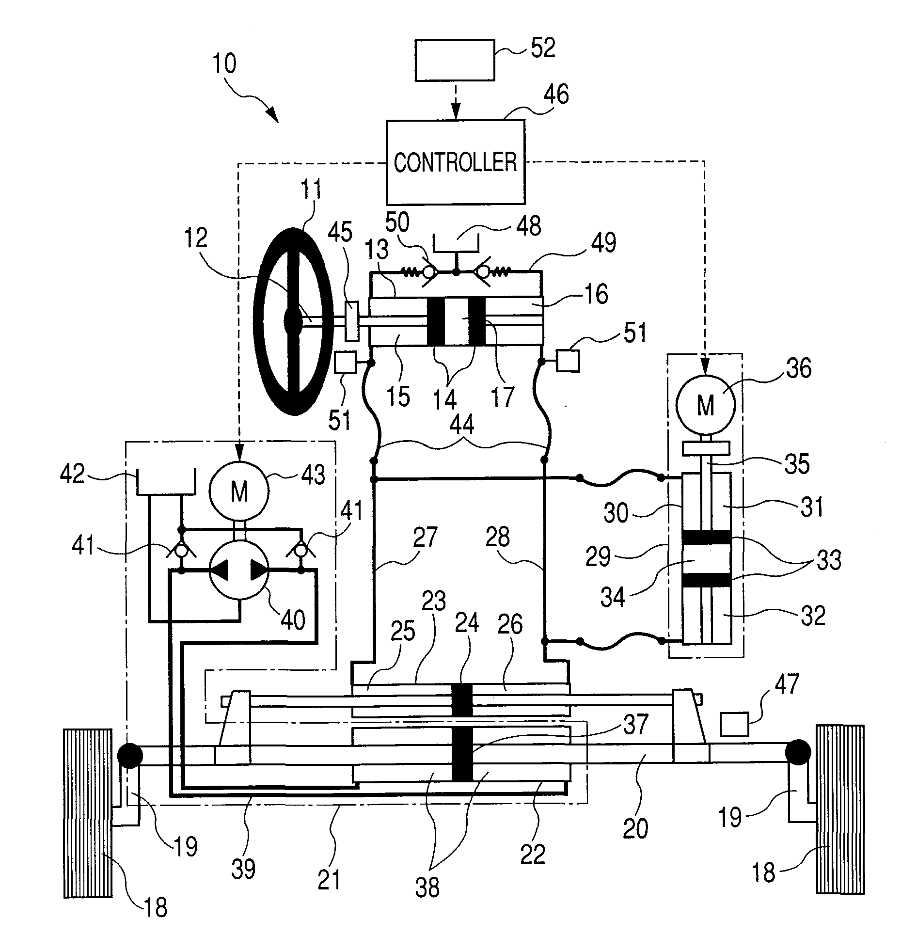
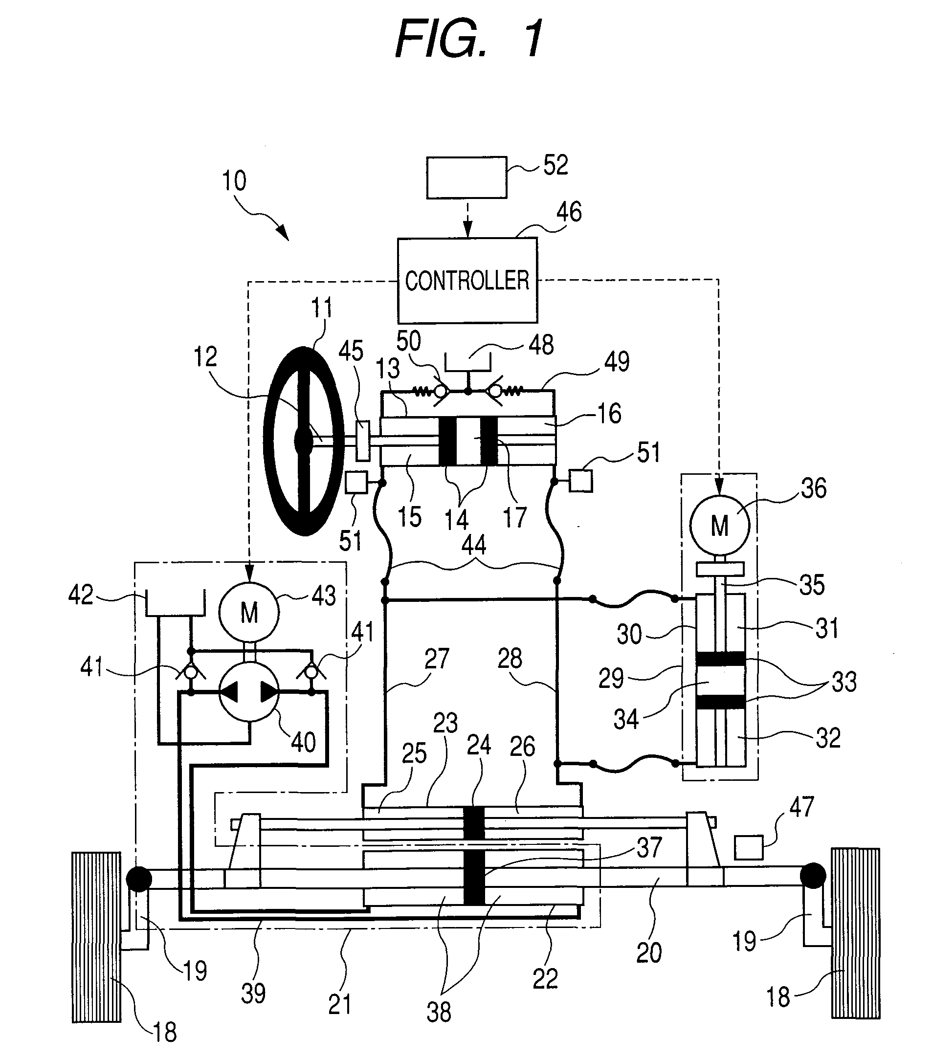
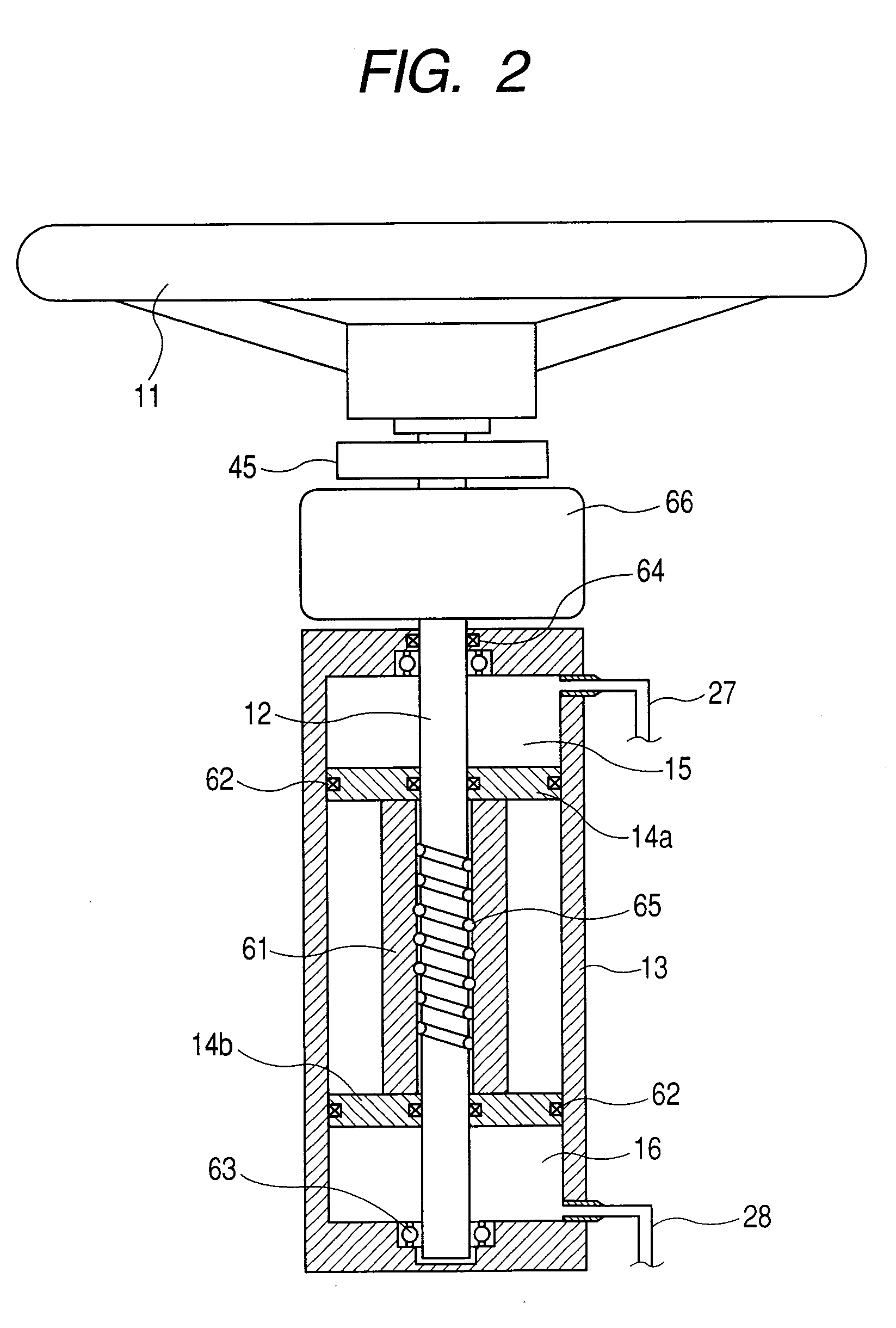
[0064]A preferred embodiment of the present invention will be described with reference to a first embodiment. FIG. 1 illustrates an overall configuration of a steering system 10 according to the present invention. In this figure, a reference numeral 11 represents a steering wheel, which is connected to an input cylinder 13 through an input shaft 12. A piston 14 fluid tightly defines first and second hydraulic chambers 15 and 16 in the input cylinder 13. A rotary motion of the steering wheel 11 is converted to a linear motion of the piston 14 by a transmission mechanism 17.

[0065]A steerable vehicle wheel 18 is connected to a steering axle 20 via a knuckle arm 19. The steering axle 20 is provided with: a power cylinder 22 serving as an output of a steering actuator 21; and an output cylinder 23 parallel thereto. A piston 24 connected to the steering axle 20 is provided in the output cylinder 23, and fluid tightly defines third and fourth hydraulic chambers 25 and 26. The first and sec...

embodiment 2

[0090]A second embodiment of the present invention will be described in detail with reference to FIGS. 7 to 9. Only the parts of the configuration different from the first embodiment will be described in the following. The parts of the configuration similar to those of the first embodiment are assigned the same reference numerals, and are not repeatedly described herein.

[0091]A steering system according to this embodiment includes the first and second hydraulic circuits described in the first embodiment and, in addition to these, third and fourth hydraulic circuits of a similar configuration to the first and second hydraulic circuits.

[0092]A steering wheel 11 is connected to a second input cylinder 213 via an input shaft 12. In the second input cylinder 213, a piston 214 fluid tightly defines ninth and tenth hydraulic chambers 215 and 216. A transmission mechanism 217 converts rotary motion of the steering wheel 11 to linear motion of the piston 214.

[0093]Further, a second output cy...


PUM


Abstract

A steering system, comprising: an input cylinder having a first hydraulic chamber and a second hydraulic chamber; a transmission mechanism, wherein a transmission efficiency for converting and transmitting a linear motion of the input cylinder to a rotary motion of a steering wheel is less than a transmission efficiency for converting and transmitting the rotary motion of the steering wheel to the linear motion of the input cylinder; an output cylinder connected to a steerable vehicle wheel and having a third hydraulic chamber and a fourth hydraulic chamber; a first hydraulic passage for connecting the first hydraulic chamber to the third hydraulic chamber; a second hydraulic passage for connecting the second hydraulic chamber to the fourth hydraulic chamber; a flow rate control mechanism for exchanging hydraulic oil with: a first hydraulic circuit including the first and third hydraulic chambers and the first hydraulic passage; and a second hydraulic circuit including the second and fourth hydraulic chambers and the second hydraulic passage, in order to adjust a ratio of hydraulic oil quantities in the first and second hydraulic circuits; a steering actuator for providing the steerable vehicle wheel with a steering power assistance; anda controller for cooperatively controlling the flow rate control mechanism and the steering actuator.

Description

CLAIM OF PRIORITY[0001]The present application claims priority from Japanese application serial No. 2006-279401, filed on Oct. 13, 2006, the content of which is hereby incorporated by reference into this application.BACKGROUND OF THE INVENTION[0002]1. Field of the Invention[0003]The present invention relates to vehicle steering system for setting the ratio of the steered angle of a wheel tire relative to the steering angle of a steering wheel depending on a driving situation without causing any sensation of discomfort to a driver.[0004]2. Prior Art[0005]Conventionally, a technology called steer-by-wire is known which connects a steering wheel to a steerable vehicle wheel via electric signals and utilizes an electric control for improving performance and for securing mountability into vehicles or vehicle cabin space. However, such a device lacks reliability against an electric failure, etc. and has difficulty in transferring a reaction force of a road surface applied to a steering wh...

Claims


Application Information

Patent Timeline
Patent Type & Authority Applications(United States)
IPC IPC(8): B62D5/06
CPCB62D3/14B62D5/30B62D5/065B62D5/003
Inventor ITO, TAKAHIROYOKOYAMA, ATSUSHISASAKI, MITSUO
Owner HITACHI LTD
Why Eureka
Try Eureka