Battery pack and connection system thereof

a battery pack and connection system technology, applied in the field of battery packs, can solve the problems of affecting the service life of secondary cells, and affecting the operation of secondary cells, so as to prevent the occurrence of failures or malfunctions, reduce the influence of electromagnetic interference, and respond quickly.

Inactive Publication Date: 2009-02-12
PANASONIC CORP
View PDF4 Cites 81 Cited by
  • Summary
  • Abstract
  • Description
  • Claims
  • Application Information

AI Technical Summary

Benefits of technology

[0018]According to the foregoing structure, the battery pack is connected to the charging device or the loading device only by the two positive and negative electric power connection terminals being a direct-current power transmission line, and the information signal sending means can send the required identification information or the operating state detection information in response to the request from the charging device or the loading device received by the information signal receiving means through the electric power connection terminal. The charging device or the loading device can judge compatibility on the basis of the identification information transmitted through the electric power connection terminal, and it is possible to prevent the occurrence of a failure or a malfunction due to the connection of an incompatible battery pack before it happens. The charging device or the loading device can judge the operating state of the battery pack from the operating state detection information, and it is possible to detect a malfunction such as the occurrence of something unusual and quickly respond thereto. Also, the connection only by the two terminals reduces the influence of electromagnetic interference and electrostatic destruction and hence can prevent the occurrence of damage and a malfunction and the like.
[0019]In each of the foregoing structures, the battery pack is electrically connected to the charging device or the loading device only by two positive and negative connection terminals. Therefore, the electric connection between the battery pack and the charging device or the loading device can not only be simplified and miniaturized, but also receives the little influence of electromagnetic interference through an information transmission line and resists the influence of electrostatic destruction.

Problems solved by technology

The more the numbers of the connection terminals increases, the more the connection terminals are susceptible to electromagnetic interference (EMI) and electrostatic destruction.
Accordingly, there is the fear of influence such as degradation in function, a malfunction, the disappearance of stored information, and the like.
Also, the device is difficult to miniaturize due to upsizing of the connection terminals and costs tend to increase due to the number of man-hours required for wiring.

Method used


Image

  • Battery pack and connection system thereof
  • Battery pack and connection system thereof
  • Battery pack and connection system thereof

Examples


first embodiment

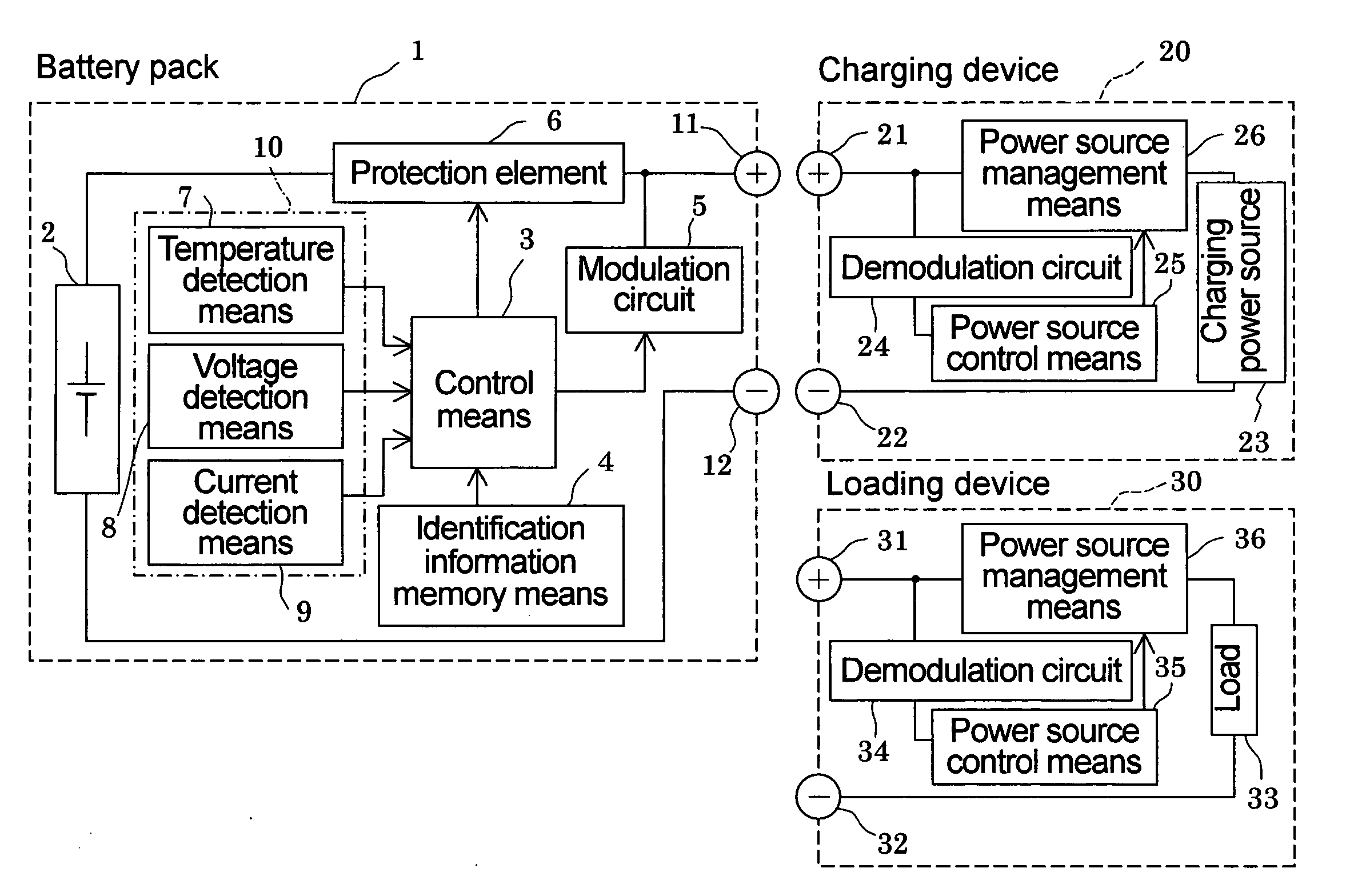
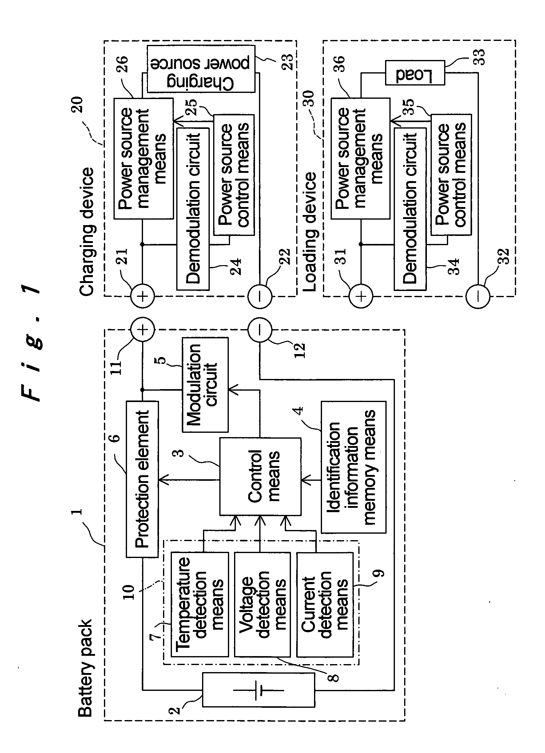
[0043]FIG. 1 shows a battery pack 1 and a connection system of the battery pack which is composed of a charging device 20 and a loading device 30 connected to the battery pack 1 according to the present invention. When a secondary battery 2 of the battery pack 1 is charged, a positive charge and discharge terminal 11 of the battery pack 1 is connected to a positive charge terminal 21 of the charging device 20 and a negative charge and discharge terminal 12 is connected to a negative charge terminal 22 so that charging energy is supplied from the charging device 20 to charge the secondary battery 2. When the battery pack 1 is connected to the loading device 30 which operates by discharging energy from the battery pack 1, the positive charge and discharge terminal 11 is connected to a positive discharge terminal 31 of the loading device 30 and the negative charge and discharge terminal 12 is connected to a negative discharge terminal 32 so that the loading device 30 operates by discha...

third embodiment

[0076]In the foregoing third embodiment, the carrier wave modulated with the information is transmitted through the direct-current power transmission line to transmit information, but the charging current may be subjected to a pulse modulation with digital information to transmit the information. When the electric current is subjected to the pulse modulation with the digital information to transmit the information, similarly as in the case of subjecting the predetermined carrier wave to the predetermined modulation method to carry out communication as described above, the information can be bidirectionally transmitted between the battery pack and the charging device or the loading device. When information from the battery pack 50 is transmitted to the charging device as shown in FIG. 3, the control means 3 allows the modulation circuit 51 to modulate the switching element 52 to transmit variation in an electric current to the current detecting element 61 in the charging device 60, t...


PUM


Abstract

In a battery pack (1), control means (3) reads identification information or operating state detection information out of identification information memory means (4) or battery operating state detection means (10) and inputs it to a modulation circuit (5). The modulation circuit (5) modulates the information into an information signal which can be superimposed on a direct-current power transmission line and sends it to a charging device (20) or a loading device (30) through a positive charge and discharge terminal (11). The charging device (20) or the loading device (30) demodulates the sent information signal to take out the identification information or the operating state detection information and allows power source control means (25, 35) to control the output of charging energy from a charging power source (23) or the output of discharging energy to a load (33). Thus, in addition to the transmission of direct-current power, information can be transmitted only by the connection of two positive and negative terminals.

Description

TECHNICAL FIELD[0001]The present invention relates to a battery pack using a secondary battery and a connection system for connecting the battery pack to a charging device or a loading device. The charging device is defined as a device which is connected to a battery pack to supply charging energy to a secondary battery. The loading device is defined as a device which is connected to a battery pack to be operated by the discharging energy of a secondary battery.BACKGROUND ART[0002]A battery pack using a secondary battery is widely used as a power source of portable electronic equipment such as a cellular phone, a notebook personal computer (hereinafter called a notebook PC), and a PDA. The battery pack is appropriately provided with a function of protecting a secondary battery from over-charge, over-discharge, a short circuit, and the like, a function of calculating and displaying the amount of remaining capacity, a function of communicating with a charging device and a loading devi...

Claims


Application Information

Patent Timeline
Patent Type & Authority Applications(United States)
IPC IPC(8): H02J7/00H02J7/02H02J13/00
CPCH01M10/46H01M10/48H02J7/0031H02J7/0077H04B2203/5454H02J2007/0098H04B2203/5416H04B2203/547H04B3/548H02J2007/0001H02J7/00045H01M10/4257H02J7/00712Y02E60/10H01M10/42H02J7/00
Inventor KITAGAWA, KATSUNORI
Owner PANASONIC CORP
Why Eureka
Try Eureka