Rotary encoder and method for operation of a rotary encoder

Active Publication Date: 2009-02-12
DR JOHANNES HEIDENHAIN GMBH
View PDF3 Cites 21 Cited by
  • Summary
  • Abstract
  • Description
  • Claims
  • Application Information

AI Technical Summary

Benefits of technology

[0008]Example embodiments of the present invention provide a rotary encoder which, as a result

Problems solved by technology

Such conventional rotary encoders have the disadvantage, for example, that they are only a

Method used


Image

  • Rotary encoder and method for operation of a rotary encoder
  • Rotary encoder and method for operation of a rotary encoder
  • Rotary encoder and method for operation of a rotary encoder

Examples


Example

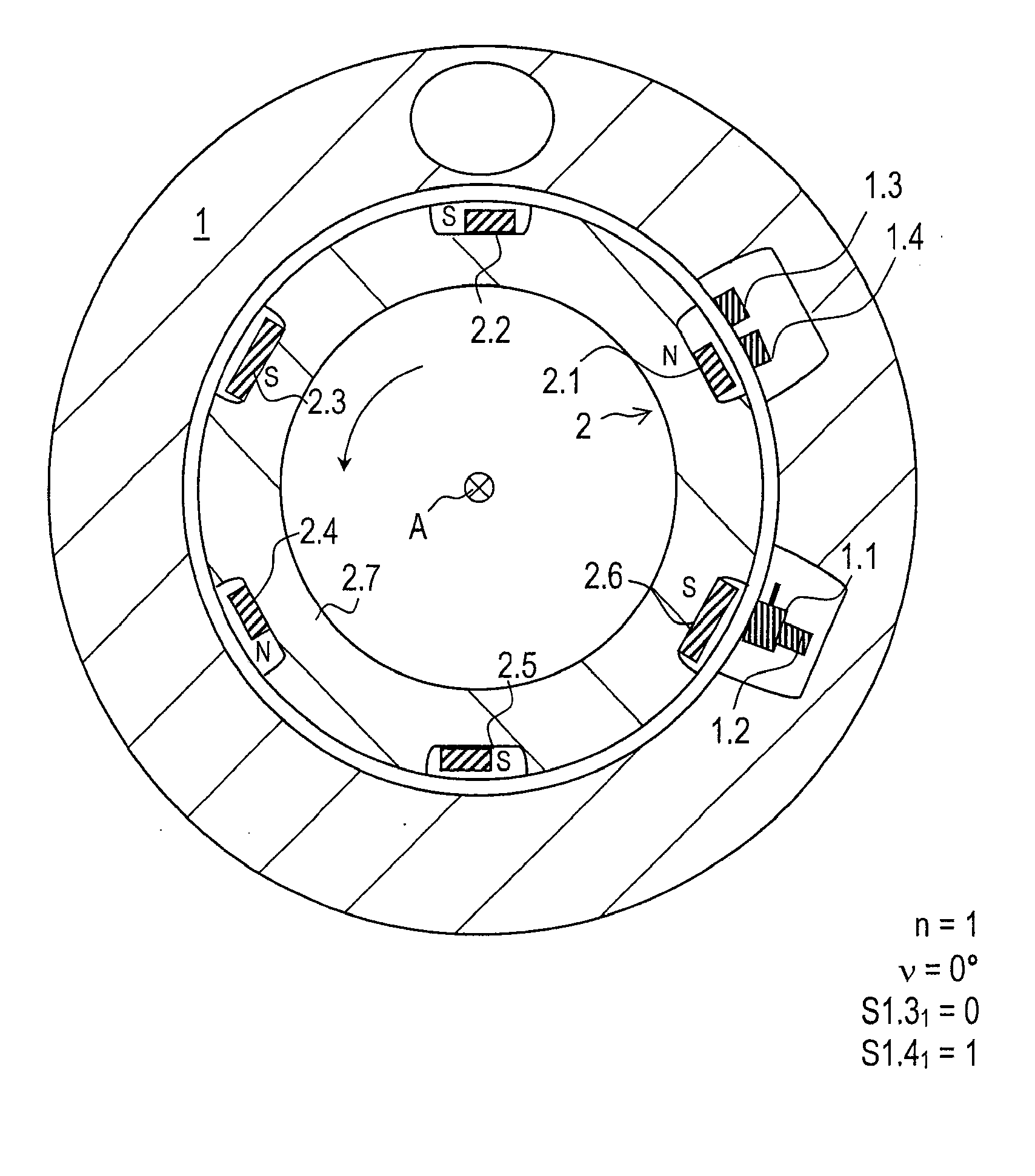
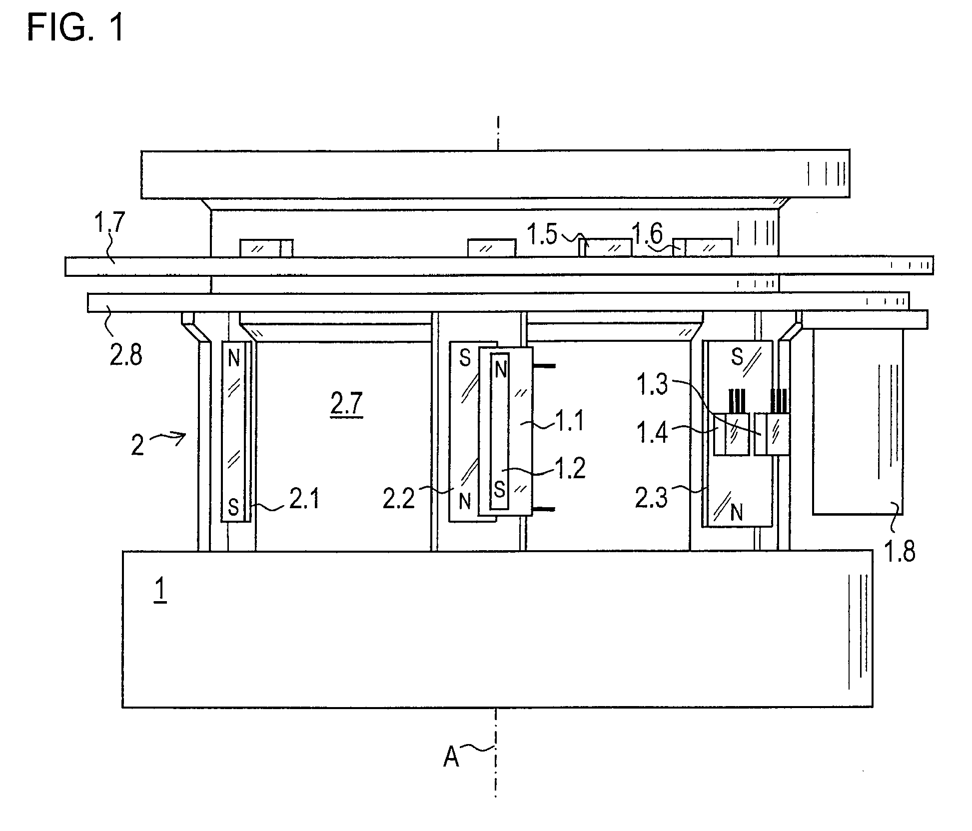
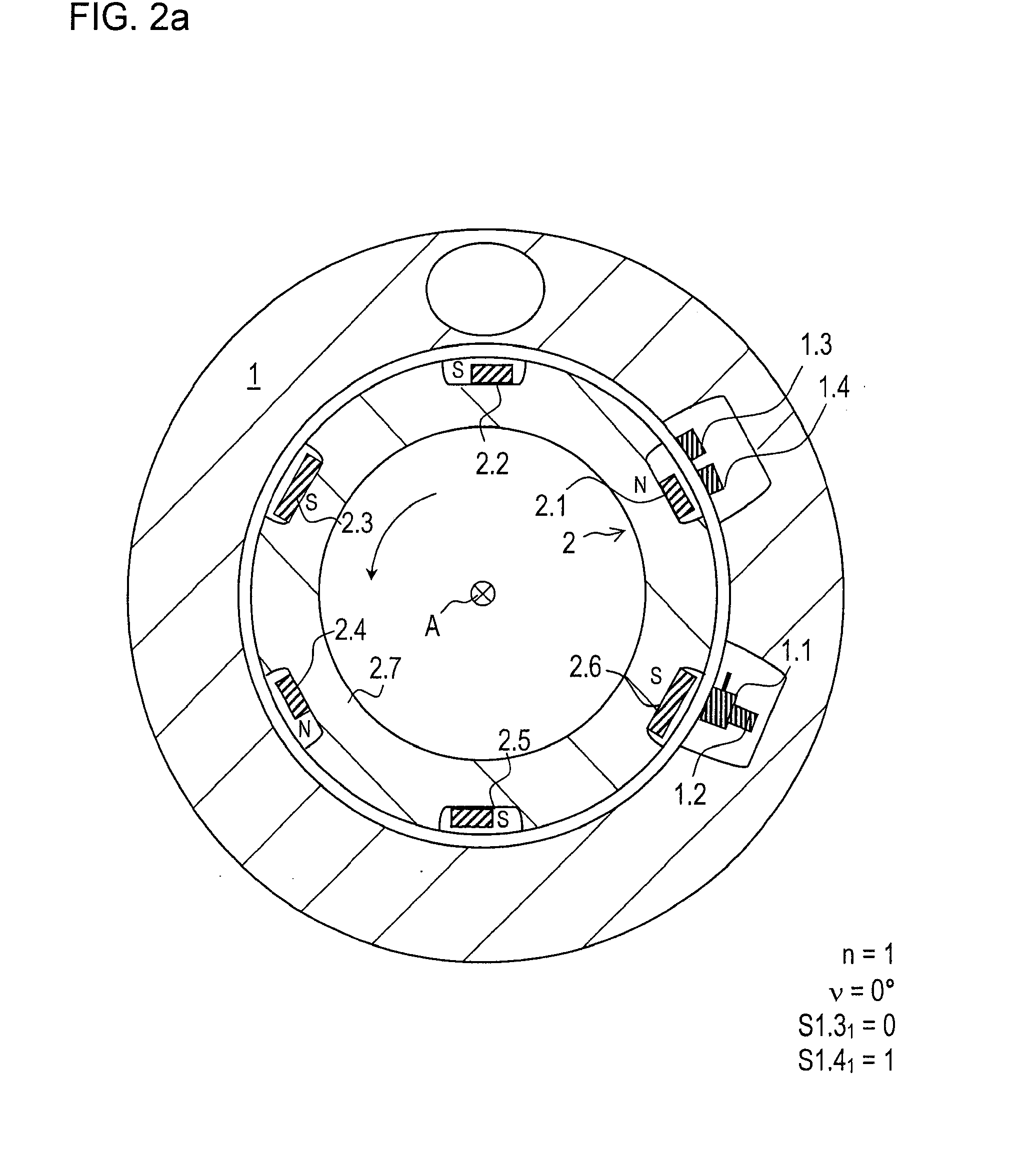
[0045]FIG. 1 shows a part of a rotary encoder according to an example embodiment of the present invention. The rotary encoder has a first component group, which in the exemplary embodiment illustrated, is used as stator 1. As a second component group, a rotor 2 is arranged in a manner allowing rotation about an axis A as against stator 1.

[0046]Stator 1 includes a pulse wire 1.1 or Wiegand sensor as a triggering sensor, which is formed of a special alloy having a magnetically hard metal as sheath and a magnetically soft metal as core. As soon as an external magnetic field exceeds a specific field intensity, a sudden magnetic reversal of the core takes place, a voltage pulse thereby being induced in a coil of pulse wire 1.1, i.e., pulse wire 1.1 triggers a voltage pulse.

[0047]A reset magnet 1.2 is arranged parallel to the longitudinal extension of pulse wire 1.1. Reset magnet 1.2 is sufficiently strong that as soon as an external magnetic field with corresponding polarity moves away a...


PUM


Abstract

A rotary encoder includes two component groups arranged in a manner allowing rotation relative to each other about an axis, the first component group having a triggering sensor and a plurality of magnetic sensors. The second component group includes a first magnet, a second magnet, and a third magnet. The component groups are configured such that, in response to a full revolution, the magnetic field of the first magnet and of the third magnet are detectable by the magnetic sensors. A trigger signal is able to be generated by the triggering sensor due to the second magnet and the third magnet, while the first magnet does not bring about a triggering of a trigger signal by the trigger sensor.

Description

CROSS-REFERENCE TO RELATED APPLICATIONS[0001]The present application claims priority to Application No. 10 2007 034 815.2, filed in the Federal Republic of Germany on Jul. 25, 2007, and to Application No. 10 2008 030 201.5, filed in the Federal Republic of Germany on Jun. 25, 2008, each of which is expressly incorporated herein in its entirety by reference thereto.FIELD OF THE INVENTION[0002]The present invention relates to rotary encoders and to methods for operation of rotary encoders.BACKGROUND INFORMATION[0003]Rotary encoders are frequently used for determining the angular position of two machine parts rotatable relative to each other. Often, such rotary encoders are employed as measuring devices for determining the absolute angular position over multiple revolutions (multiturn function) of corresponding drive shafts. In so doing, the rotary motion is recorded incrementally or absolutely. In connection with gear racks and gear wheels or with threaded spindles, linear motions can...

Claims


Application Information

Patent Timeline
IPC IPC(8): G01B7/30
CPCG01D5/245G01D5/145
Inventor FISCHER, PETER
Owner DR JOHANNES HEIDENHAIN GMBH
Why Eureka
Try Eureka