
Low vision aid device

a technology of low vision and aid device, which is applied in the field of low vision aid device, can solve the problems of reducing affecting the ability of people to read, write, and recognize faces, and affecting the ability of people to discriminate objects or face recognition, so as to reduce the size of the low-vision goggle of the user

Inactive Publication Date: 2009-02-12
BEN GURION UNIVERSITY OF THE NEGEV +1
View PDF4 Cites 16 Cited by
  • Summary
  • Abstract
  • Description
  • Claims
  • Application Information

AI Technical Summary

Benefits of technology

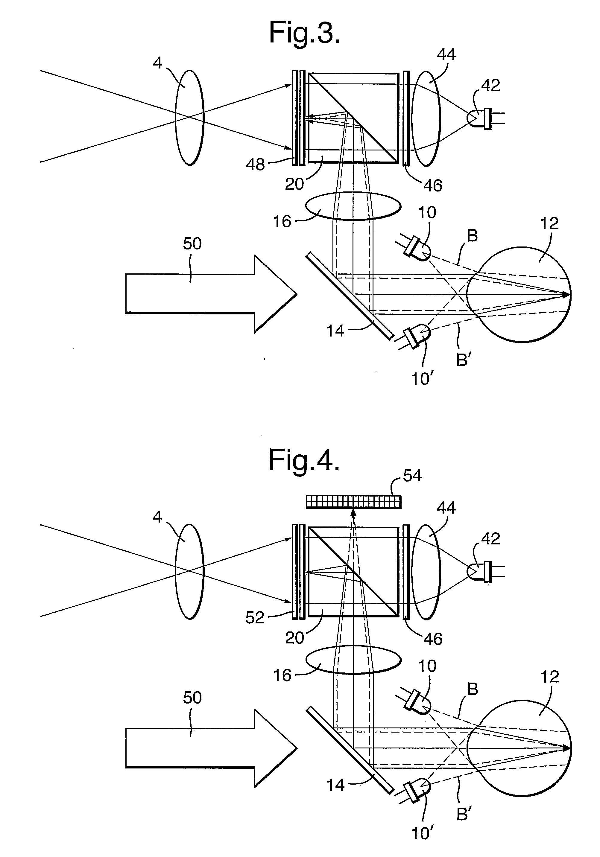
[0013]In accordance with the present invention there is therefore provided a low-vision aid device, comprising a scene-display imager producing a signal pattern composed of an array of pixels; means for illuminating the retina of said eye with near IR (NIR) radiation for eye tracking, to be reflected from the retina of the eye; an eye-retina tracking imager, and an image transceiver device (ITD) having means capable of providing both functions of eye imaging as well as image display by selectively rotating the polarization of individual pixels of said array of pixels of the signal pattern, to allow the transference of selected portions of said signal pattern to reach the retina of the eye.

Problems solved by technology

People with low vision typically have significantly reduced visual acuity and a significant loss of contrast sensitivity, often in combination with visual field loss.
These impairments cause a number of disabilities including difficulty with reading, writing, recognizing faces, orientation and mobility, and other activities of daily life.
Thus, the partial or complete loss of vision acuity in the central (fovial) region of the retina caused by aged-related macular degeneration (AMD) will deprive people of their ability to read, discriminate objects or recognize faces.
The loss of peripheral vision caused for example by retinitis pigmentosa (RP) results in the loss of the peripheral field, which is critically needed for orientation and mobility.
Other local vision losses will result in the appearance of visual “holes” or scotomas, where persons lose partial areas of their visual field of view.
While there exist a variety of low vision aid instruments, they are almost all limited to static optical correction, e.g., mini-telescope mounted on eye-glasses, whereas the preferred solution calls for an adaptive correction including pre-processing and conditioning of the input imagery.
There also exists no practical solution for those low vision persons who experience mobility problems.
Recently there have been several attempts to provide some measure of basic Image conditioning in mobile, head-mounted devices, however these devices fall quite short of the required solution in that they fail to provide:a) the necessary image re-mapping and image processing;b) See-through capability; andc) Compact size head-mounted gear.
That is why the large, bulky head mounted (HM) goggle, while providing better functionally, is usually unacceptable.

Method used


Image

  • Low vision aid device
  • Low vision aid device
  • Low vision aid device

Examples


Embodiment Construction

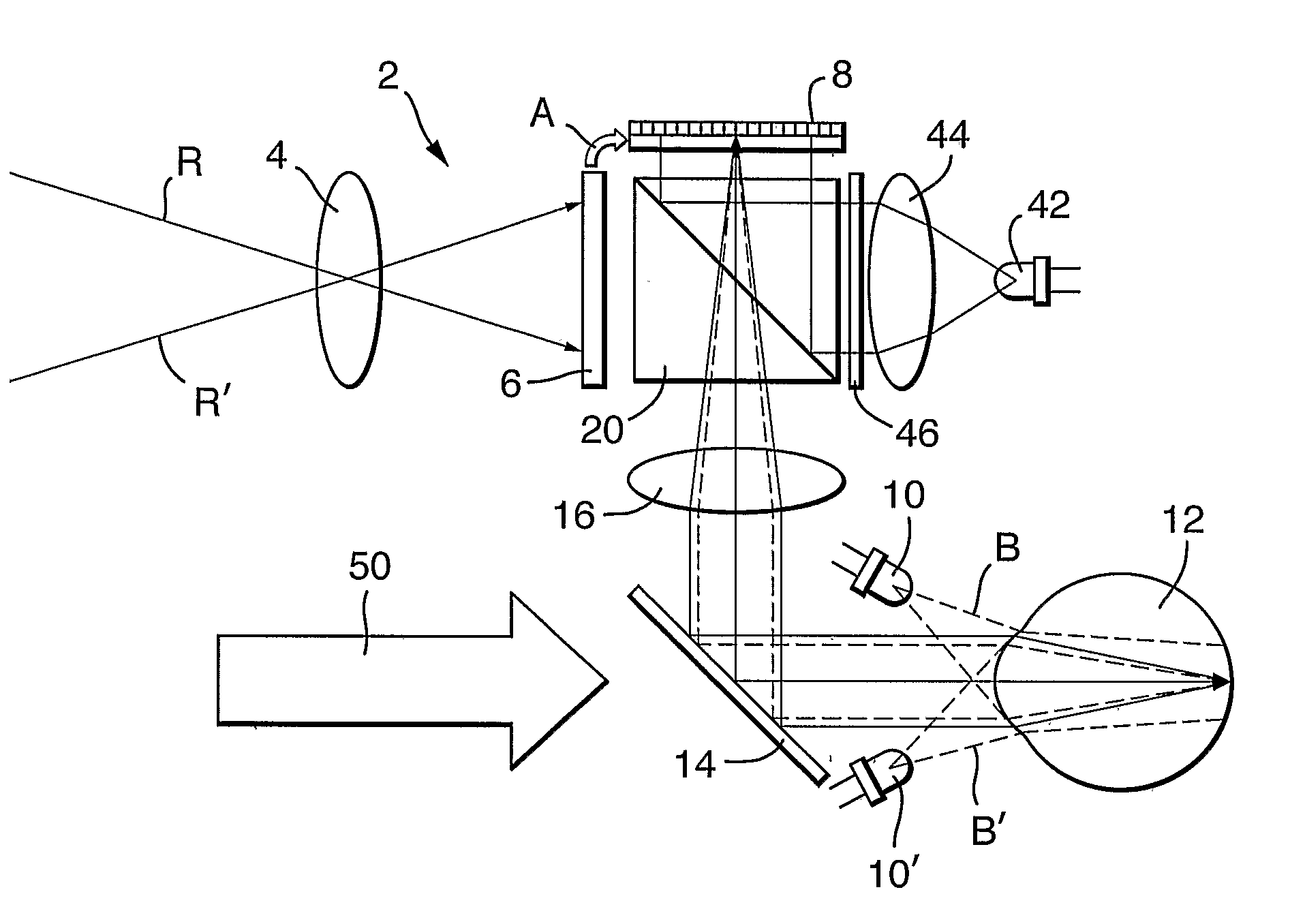
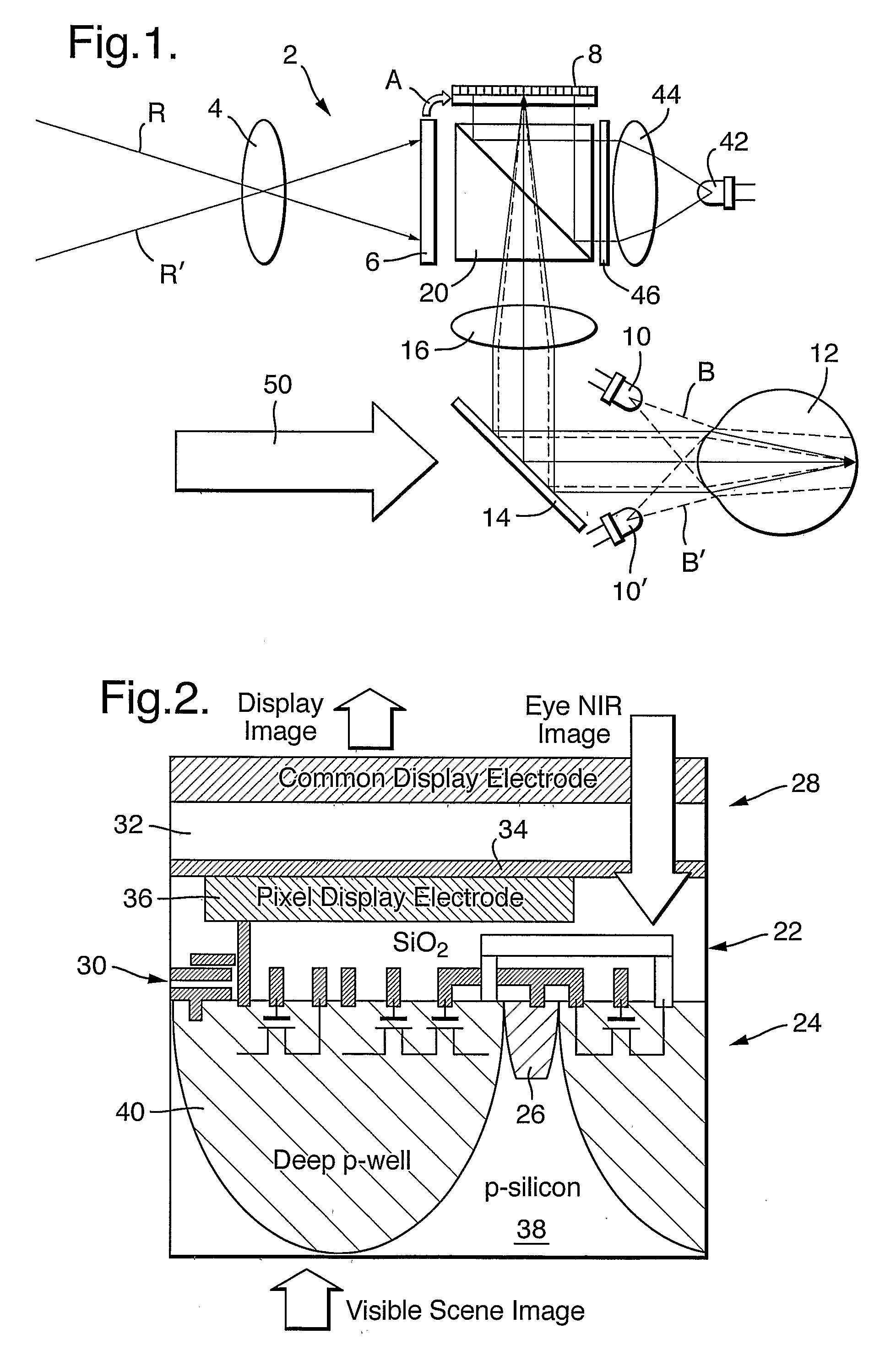
[0021]Referring to FIG. 1, there is illustrated an embodiment of a low-vision aid device 2 according to the present invention. Starting with the two crossed rays R, R′, which indicate the observed scenery, after passing a scene-imager optics 4, is imaged by a scene imager 6, which can be constituted by a simple CMOS imager. Following appropriate image processing of the scene information, the processed image is transferred, as indicated by the arrow A, to the display part of the eye-tracker(imager) / display (image transceiver device) ITD 8 for display. The NIR light emitting diodes (NIR-LEDs) 10, 10′, located adjacent to the viewer's eye 12, radiate R-polarized NIR beams B, B′ into the observer's eye 12. The R-polarized NIR beams are reflected from the retina, carrying the retinal image down the optical path, as shown by the broken lines. The image beam is then reflected by the non-polarizing beam splitter (NBS) 14, passes through a display eyepiece / eye tracker optics 16 to a polarizi...


PUM


Abstract

There is provided a low-vision aid device, including a scene-display imager producing a signal pattern composed of an array of pixels, a near IR illuminator for illuminating the retina of the eye with radiation for eye tracking, to be reflected from the retina of the eye, an eye-retina tracking imager, and an image transceiver device capable of providing both functions of eye imaging as well as image display by selectively rotating the polarization of individual pixels of the array of pixels of the signal pattern, to allow the transference of selected portions of the signal pattern to reach the retina of the eye.

Description

FIELD OF THE INVENTION[0001]The present invention relates to a low-vision aid device and more particularly to an image transceiver device (ITD), for retinal re-mapping for visual enhancement.BACKGROUND OF THE INVENTION[0002]Between 2 to 4% of the total population and up to 60% of our aging population suffer from vision loss not readily correctable with ordinary optical or medical intervention. People with low vision typically have significantly reduced visual acuity and a significant loss of contrast sensitivity, often in combination with visual field loss. These impairments cause a number of disabilities including difficulty with reading, writing, recognizing faces, orientation and mobility, and other activities of daily life. Thus, the partial or complete loss of vision acuity in the central (fovial) region of the retina caused by aged-related macular degeneration (AMD) will deprive people of their ability to read, discriminate objects or recognize faces. The loss of peripheral vi...

Claims


Application Information

Patent Timeline
IPC IPC(8): A61B3/14
CPCG02B5/30G02B27/0093G02B2027/0187G02B27/022G02B27/0172
Inventor EFRON, UZIDAVID, YIZHAKAPTER, BORISTHIRER, NONELBAAL-ZEDAKA, ITZHAK
Owner BEN GURION UNIVERSITY OF THE NEGEV
Learn More