Light emitting diode illumination system

Active Publication Date: 2009-02-12
LUMENCOR
View PDF0 Cites 85 Cited by
  • Summary
  • Abstract
  • Description
  • Claims
  • Application Information

AI Technical Summary

Problems solved by technology

The problems associated with these lamp technologies, however, include poor luminous efficacy thereby requiring high power and associated means of cooling, short lifetime, high voltage operation (typically kilovolts required to turn them on), high cost, and use of mercury which is

Method used


Image

  • Light emitting diode illumination system
  • Light emitting diode illumination system
  • Light emitting diode illumination system

Examples


example 1

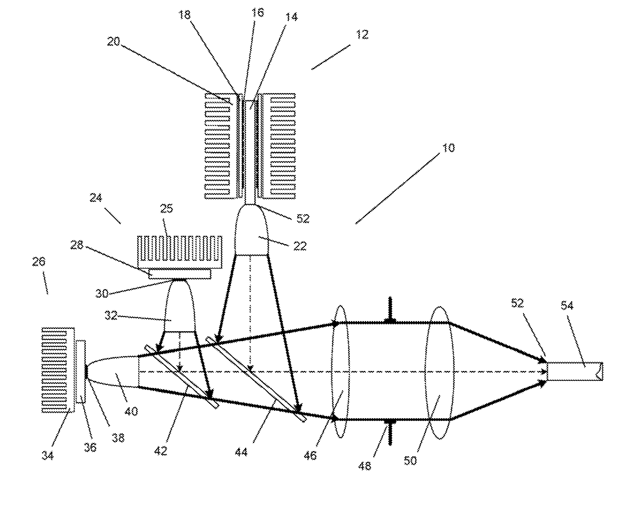
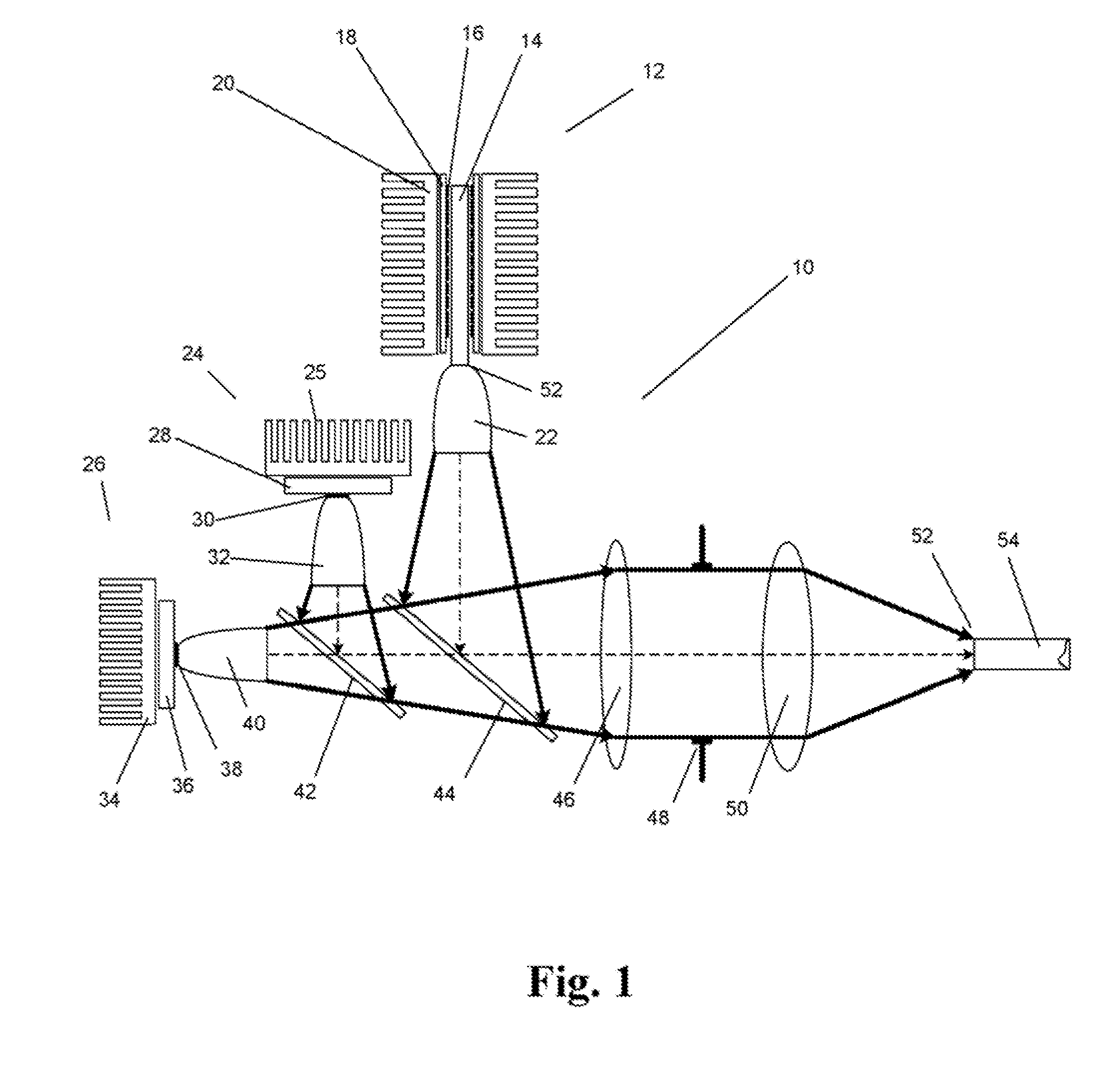
[0078]In an embodiment of the invention, a rod with 0.8 mm square cross-section is coupled to a truncated ball lens and further magnified by a small plano-convex lens, finally collimated by a 38 mm focal length (FL) asphere. Allowing for two dichroic combining mirrors leaves an air space of 68 mm. The energy can be refocused with another asphere, into a 3 mm liquid light guide with an effective 0.3 NA.

[0079]FIG. 14 shows that at the refocus, a rectangular image of about 3.6 mm square is obtained; appropriate for alignment and optical tolerance buildups.

[0080]FIG. 13 shows that launching rays within 55 degrees in the YAG, 40% can be transferred into the LLG. In FIG. 15, a representative output from a four color light engine is provided. The specific colors (solid line) shown are UV 1510 (395 nm), 1520 Cyan (485 nm), 1530 Green (560 nm), and 1540 Red (650 nm). Such a range of colors can be generated by a combination of diode lasers, LEDs and luminescent light pipes. The band positions...


PUM


Abstract

In various embodiments of the invention, a unique construction for Light Emitting Diodes (LEDs) with at least one luminescent rod and extracting optical elements is used to generate a variety of high brightness light sources with different emission spectra. In an embodiment of the invention, forced air cooling is used to cool the luminescent rod. In an embodiment of the invention, totally internal reflected light can be redirected outward and refocused. In another embodiment of the invention, light emitted by the luminescent rod is out-coupled for use in a variety of applications. In various embodiments of the invention, a plurality of independent narrow band colors can be coaxially combined.

Description

PRIORITY CLAIM[0001]This application claims priority to: (1) U.S. Provisional Patent Application Ser. No. 60 / 954,140, entitled: “LIGHT EMITTING DIODE ILLUMINATION SYSTEM”, inventor: Thomas J. Brukilacchio, filed Aug. 6, 2007, which application is incorporated herein by reference in its entirety.CROSS REFERENCE TO RELATED APPLICATIONS[0002]This application is related to the following application, which was filed on Aug. 5, 2008 herewith:[0003]“LIGHT EMITTING DIODE ILLUMINATION SYSTEM” by Thomas J. Brukilacchio, application Ser. No. 12 / 186,475, Attorney Docket No. LUMEN-01019US0 SRM / AGC which application is incorporated herein by reference in its entirety.FIELD OF THE INVENTION[0004]This invention, in general, relates to high brightness illumination sources and more particularly to the use of Light Emitting Diodes (LEDs) as a source of illumination.BACKGROUND OF THE INVENTION[0005]There is a significant need for high brightness broad band illumination sources to provide optical fiber ...

Claims


Application Information

Patent Timeline
IPC IPC(8): F21S19/00
CPCA61B1/0653A61B1/0684A61N2005/005A61N2005/0652F21Y2101/02F21Y2105/00F21Y2113/00G01N2021/6419G01N2021/6482G01N2201/0627G02B6/0006G02B23/2469G02B27/0994G02B27/1006G02B27/143G02B27/145F21V13/02G01N21/64F21K9/52F21K9/56A61B1/00163A61B1/0669A61N5/062F21Y2115/10F21Y2115/30F21V9/30F21V13/08F21V5/008F21V13/14F21K9/60F21K9/61F21Y2113/13F21V29/70F21V13/04F21W2131/205F21W2131/40F21V29/60F21V7/0066F21K9/64
Inventor BRUKILACCHIO, THOMAS J.CONNER, ARLIE R.
Owner LUMENCOR
Why Eureka
Try Eureka