Refrigerating compressor with variable-speed coils

Active Publication Date: 2009-02-12
DANFOSS COMML COMPRESSORS
View PDF2 Cites 15 Cited by
  • Summary
  • Abstract
  • Description
  • Claims
  • Application Information

AI Technical Summary

Benefits of technology

[0017]The present invention aims to remedy these drawbacks, and its aim is to provide a refrigerating compressor with variable-spee

Problems solved by technology

The compressor described in the U.S. Pat. No. 6,287,099 does, however, present a disadvantage associated with the structure of the drive shaft and the blocking piece.
In practice, when the speed of the compressor becomes high and exceeds a threshold value, the

Method used


Image

  • Refrigerating compressor with variable-speed coils
  • Refrigerating compressor with variable-speed coils
  • Refrigerating compressor with variable-speed coils

Examples


Embodiment Construction

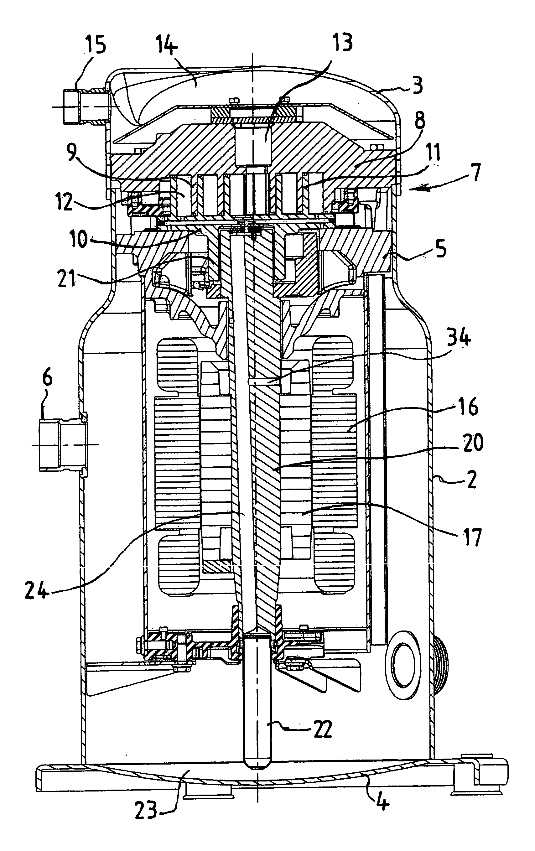
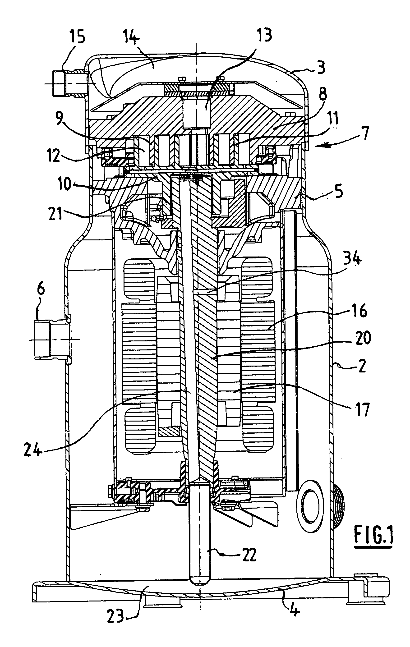
[0048]FIG. 1 describes a refrigerating compressor with variable-speed coils occupying a vertical position. However, the inventive compressor could occupy a tilted position, or even a horizontal position, without its structure being modified significantly.

[0049]The compressor represented in FIG. 1 comprises a sealed chamber delimited by a shell 2, the top and bottom ends of which are closed respectively by a cover 3 and a base 4. This chamber can be assembled notably by means of weld beads.

[0050]The intermediate part of the compressor is occupied by a body 5 which delimits two volumes, a suction volume located below the body 5, and a compression volume positioned above the latter. The shell 2 comprises a refrigerating gas inlet 6 discharging into the suction volume to direct the gas to the compressor.

[0051]The body 5 provides the mounting for a compression stage 7 of the refrigerating gas. This compression stage 7 comprises a fixed volute 8 fitted with a fixed coil 9 turned downwards...


PUM


Abstract

This refrigerating compressor comprises a sealed chamber delimiting a suction volume and a compression volume arranged respectively either side of a body contained in the chamber, and an oil injection circuit arranged to inject oil into the compression volume. The oil injection circuit comprises a moving blocking piece, operated by a centrifugal force, between a first position enabling oil injection into the compression volume and a second position preventing or limiting oil injection into the compression volume, the blocking piece being arranged to be displaced into its second position when the speed of the compressor exceeds a predetermined value.

Description

BACKGROUND OF THE INVENTION[0001]The subject of the present invention is a refrigerating compressor with variable-speed coils.[0002]The document FR 2 885 966 describes a coil compressor, also known as a scroll compressor, comprising a sealed chamber delimited by a shell and containing a suction volume and a compression volume arranged respectively either side of a body contained in the chamber. The shell delimiting the sealed chamber comprises a refrigerating gas inlet.[0003]An electric motor is positioned inside the sealed chamber, with a stator located on the outside, mounted fixed relative to the shell, and a rotor in a central position, joined to a drive shaft, in the form of a crank shaft, a first end of which drives an oil pump feeding, from oil contained in a pan situated in the bottom part of the chamber, a lubrication pipe provided in the central part of the shaft. The lubrication pipe comprises lubrication orifices level with the various bearings guiding the drive shaft.[0...

Claims


Application Information

Patent Timeline
IPC IPC(8): F01C1/02
CPCF04C18/0215F04C23/008F04C29/028F04C29/025F04C29/023
Inventor GINIES, PIERREROSSON, YVESBODART, JEAN-PAUL
Owner DANFOSS COMML COMPRESSORS
Why Eureka
Try Eureka