Sterile Tensor Cravats And Methods For Storing And Deploying Same

a tensor cravat and tensor technology, applied in the field of articulated, adjustable, lockable alignment arms, can solve the problems of difficult splinting of injuries, difficult transportation of patients to hospital in remote locations, and patient discomfort and possible aggravation of injuries, so as to achieve safe movement of patients, easy transportation, and convenient transportation.

Inactive Publication Date: 2009-02-12
BORSCHNECK ANTHONY G
View PDF7 Cites 12 Cited by
  • Summary
  • Abstract
  • Description
  • Claims
  • Application Information

AI Technical Summary

Benefits of technology

[0014]The present invention provides for improvements in splints used for transporting injured patients from a field location to a treatment facility. Such improvements include: (1) splints with radiolucent properties around and along the region of the injury, thus allowing X-ray, Cat Scan and MRI imaging of the injury without the need for removing the splint; (2) a portable splint kit which may be packaged, transported, disassembled, or reassembled in the field, quickly and efficiently; (3) splint assemblies which provide both a splinting function and apply a quantifiable and dynamic traction force to one or two broken femurs; (4) a splint modeling system having adjustment and fixation features allowing the splinting of any limb, joint or body part on any human of any size or age; and, (5) fabric tensor cravats for use with the splint assemblies and the splint modeling system, which are maintained in a sterile condition both during storage in the portable splint kit and while being deployed over open wounds on a patient's body.
[0015]The heart of the splint modeling system is an articulated, adjustable, and lockable, alignment arm. The alignment arm is comprised of two arm segments, each having one respective end pivotally attached to a respective end of an intermediate connector body. The axes for the pivotal attachments are perpendicular with respect to each other. The arm segments may be independently adjusted and selectively locked into a plurality of rotational positions about a respective axis. In use, the alignment arm is shaped adjacent and parallel to any fractured bone or joint, thereby producing a modeled structure having the same configuration and orientation as the injured limb. The procedure affords accurate splinting of the fractured member without movement or production of pain. Rotating locking knobs on the connector body ensures that the alignment arm retains the shape of the injury. Once the alignment arm is locked into the desired configuration, the arm segments are lengthened through the use of arm extenders fitted with padded material. End pads may also be installed into the free ends of the arm extenders. The assembly is then gently placed on the limb or body, and secured in position with two or more fabric cravats of variable lengths and widths. This affords safe movement of the patient, while securing the injured limbs and joints of the patient in the same position they were found by medical personnel.
[0016]The outer surface of the flexible cravats is provided with a dynamic composite elasticized loop fabric, marketed under the trademark BREATH-O-PRENE. The inner surface is provided with an opened cell foam material, embedded with nano-crystals of a silver compound, namely, silver chloride. For the purpose of securing the cravats around the limb and the modeled splint, one end of each cravat includes a short length of hook Velcro sewn thereon. The cravats are folded for storage in a unique manner which completely sterilizes the inner surface to be applied over a patient's open wounds or appendage. When deployed for use, another method of unfolding and applying the cravat, ensures that the sterility of the inner surface is maintained as the cravat is applied to the patient. These sterile cravats create a quick, secure closure member, either for binding the limb to the splint structure, or for restraining or supporting a limb, or for enclosing a wound.
[0017]Another application for certain components of the invention is to splint, for example, leg injuries also needing a pre-determined amount of traction. In this application, a bilateral traction splint assembly is provided, including a spring pulley and cable structure, entirely mounted and enclosed within a telescopic housing at the distal end of the assembly. The same arm extenders used in the articulated splint are coupled together to form a straight splint shaft, extending between a base cushion seated against the user's ischial tuberosity at the proximate end of the assembly, and an ankle cravat secured to the user's ankle at the distal end of the assembly. The splint shaft is padded on both lateral surfaces lying along the inner sides of the user's leg, providing enhanced patient comfort.
[0018]A carrying case is also provided, housing a kit comprising a disassembled bilateral traction splint, an articulated alignment arm, padded arm extenders, end pads, and a plurality of sterile fabric cravats of varying widths and lengths. In the hands of properly trained medical personnel, this kit is capable of quickly and correctly providing a traction splint, if needed, for fractured femurs, or providing a modeled splint for stabilizing a limb extending from the body of any sized adult or child.

Problems solved by technology

One recognized problem stems from the wide variety of injuries encountered, ranging from a broken arm or leg, to a dislocated shoulder.
Other problems encountered include patient discomfort and possible aggravation of the injury resulting from improper splinting.
Where the injury has occurred in the field or under the conditions of a traumatic accident, the job of splinting the injury and transporting the patient to a hospital in a remote location is particularly challenging.
Nevertheless, current medical requirements indicate the need for an improved splint device or system that is small, light and compact, for transport to remote and difficult to reach accident locations.

Method used


Image

  • Sterile Tensor Cravats And Methods For Storing And Deploying Same
  • Sterile Tensor Cravats And Methods For Storing And Deploying Same
  • Sterile Tensor Cravats And Methods For Storing And Deploying Same

Examples


Embodiment Construction

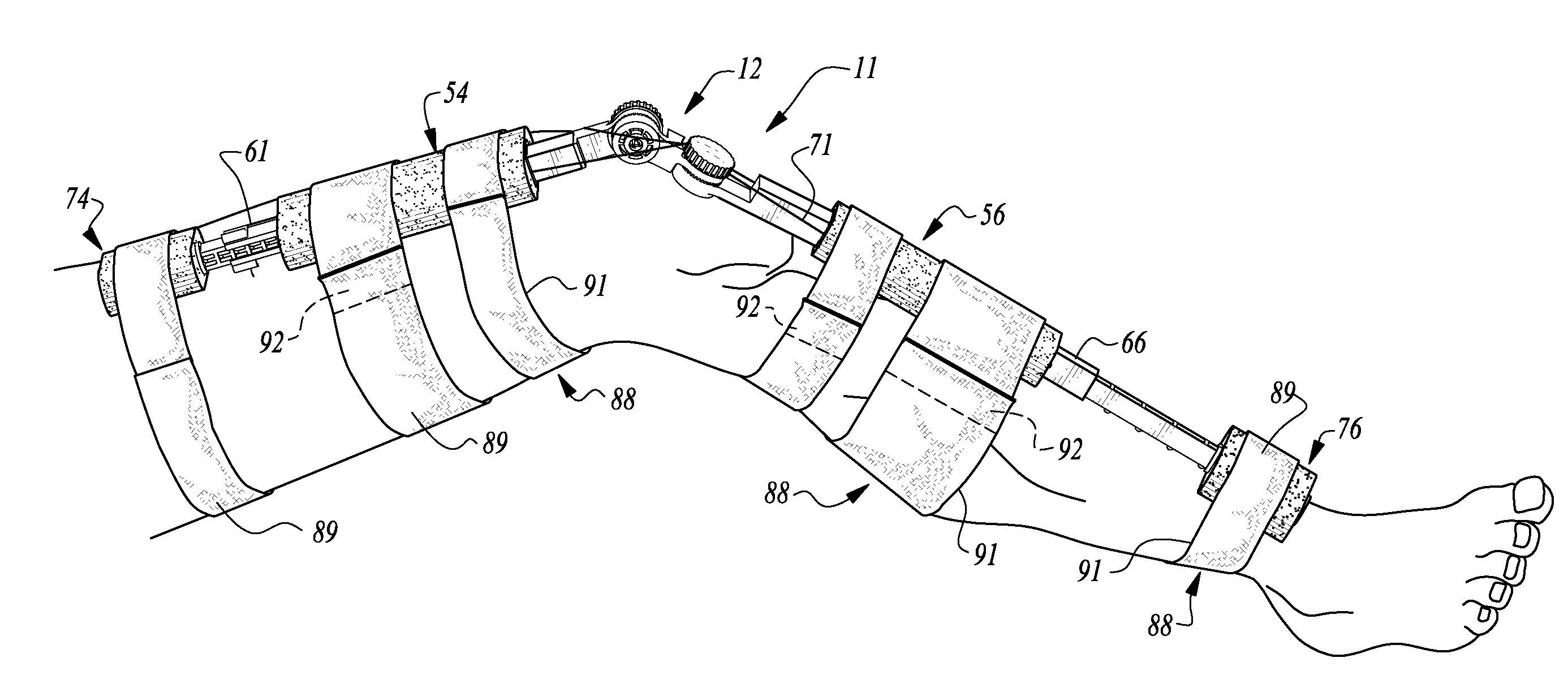
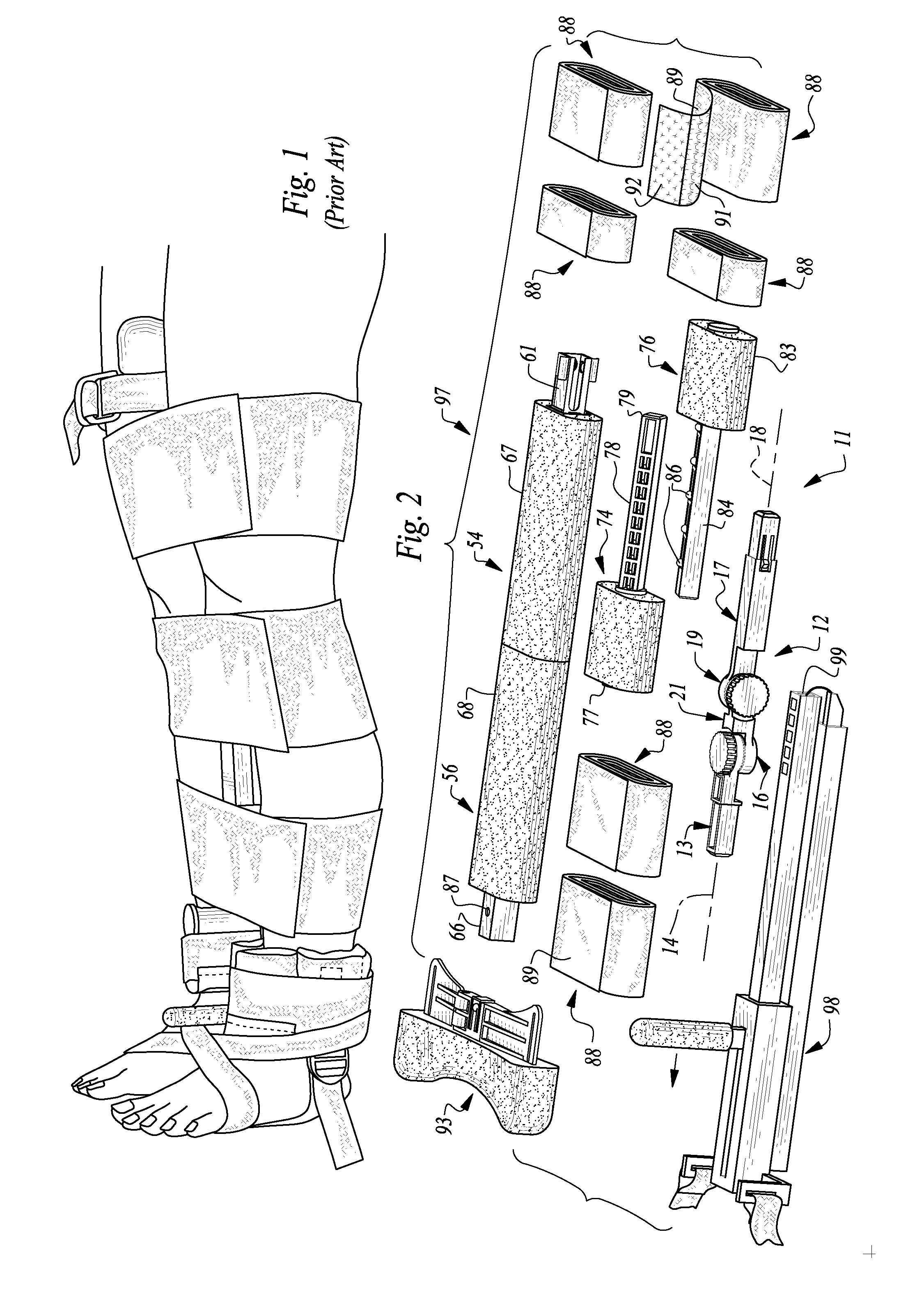
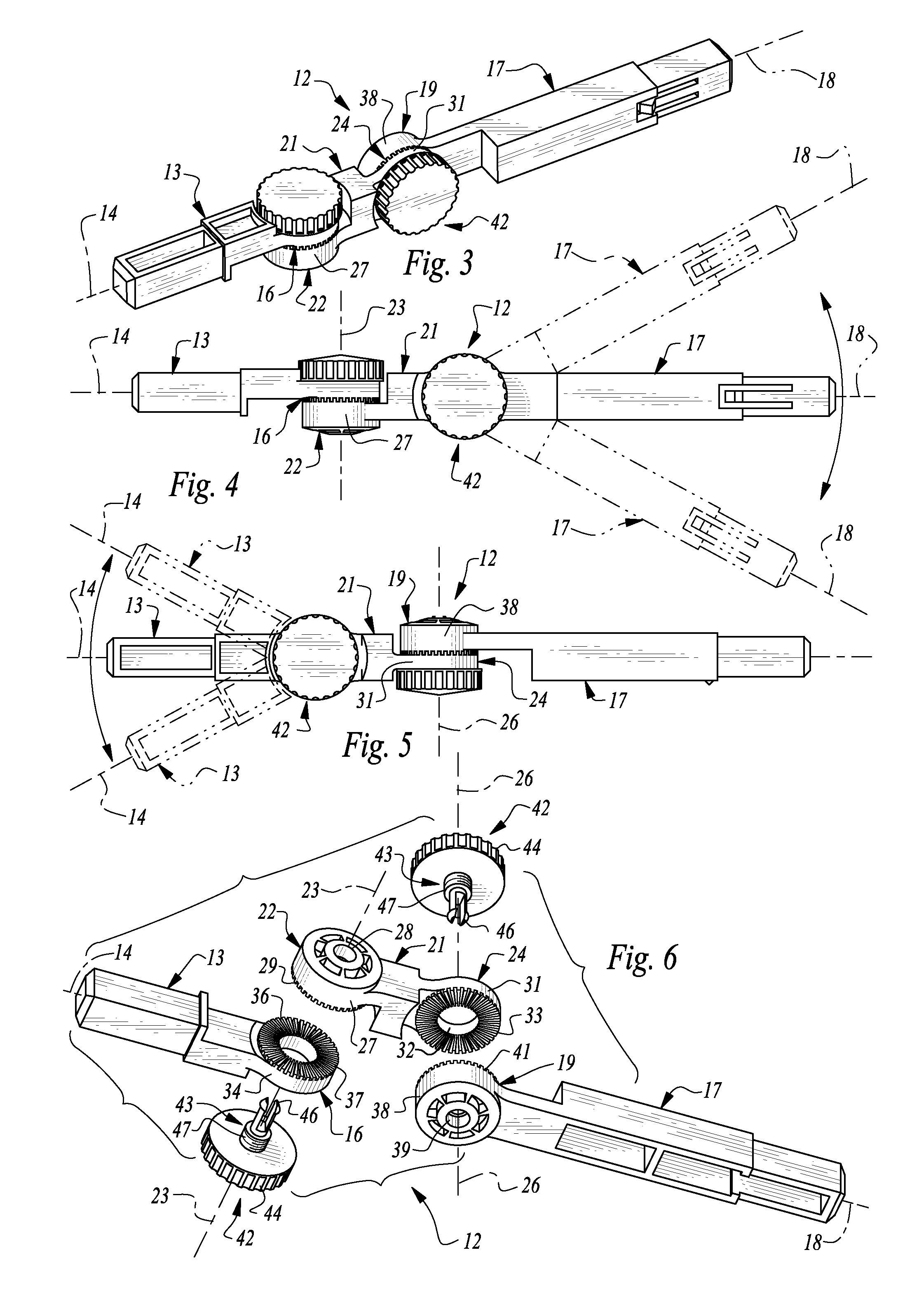
[0048]The splint apparatus 11 of the present invention comprises an articulated alignment arm 12, for modeling the orientation and configuration of an injured human limb. Alignment arm 12 includes a first elongated arm segment 13 having a longitudinal axis 14 and a respective pivot end 16, and a second elongated arm segment 17 having a longitudinal axis 18 and a respective pivot end 19. Alignment arm 12 also includes a dual-axis connector body 21 for interconnecting first arm segment 13 to second arm segment 17. Connector body 21 is provided with a first receiver 22 adapted to couple with respective pivot end 16 of first arm segment 13 and lock it at a first selected orientation about a first transverse axis 23. Connector body 21 is also provided with a second receiver 24 adapted to couple with respective pivot end 19 of second arm segment 17 and lock it at a second selected orientation about a second transverse axis 26. As is evident from FIGS. 4, 5, and 6, first transverse axis 23...


PUM

PropertyMeasurementUnit
flexibleaaaaaaaaaa
lengthaaaaaaaaaa
shapeaaaaaaaaaa

Abstract

An articulated, adjustable, and lockable alignment arm, and associated extensions and accessories, which are user manipulable to model the size and shape of the fractured limb of a patient in the field. The alignment arm is adjusted for proper orientation by setting it over the injury, and then locking the arm into a selected orientation which models the patient's limb around the area of the injury. Next, first and second arm extenders and protective end pads are used to expand the effective size of the alignment arm to form a custom splint structure. Lastly, the splint structure is secured to the patient's injured limb through the use of flexible cravats. The cravats are self-sterilizing, stored so that their sterility is maintained, and deployed so that only the sterile portion of the cravat comes into contact with a patient's skin.

Description

PRIORITY CLAIM[0001]Pursuant to the provisions of 35 U.S.C. § 119(e)(1), Applicant claims the priority of U.S. Provisional Patent Application Serial No. 60 / 897,165, filed Jan. 23, 2007.CROSS-REFERENCE TO RELATED APPLICATIONS[0002]This application is a continuation-in-part of Ser. No. 12 / 009,479, filed Jan. 18, 2008.BACKGROUND OF THE INVENTION[0003]1. Field of the Invention[0004]The invention relates generally to improvements in apparatus and methods providing medical splinting for fractured or broken human limbs, joints, and body parts. More particularly, the invention pertains to an articulated, adjustable, and lockable alignment arm, and associated extensions and accessories. These components are user manipulable in the field, to create a rigid, padded, structural model which emulates the shape of the fractured limb of a patient.[0005]By securing the structural model and the limb together with fabric tensor cravats, the injured patient may be transported comfortably and safely to ...

Claims


Application Information

Patent Timeline
Patent Type & Authority Applications(United States)
IPC IPC(8): A61F5/00A61L15/00
CPCA61F5/0125A61F2005/0158A61F2005/0134A61F5/05841
Inventor BORSCHNECK, ANTHONY G.
Owner BORSCHNECK ANTHONY G
Why Eureka
Try Eureka