Eureka AIR delivers breakthrough ideas for toughest innovation challenges, trusted by R&D personnel around the world.

Dynamic extension plate for anterior cervical fusion and method of installation

a technology of anterior cervical fusion and extension plate, which is applied in the field of controlling the kinematics of the body, can solve the problems of increased pain and suffering for patients, high invasiveness of explanting old bone fasteners and introducing new bone fasteners, and achieves less resistance to motion

Inactive Publication Date: 2009-02-12
AESCULAP INC
View PDF78 Cites 44 Cited by
  • Summary
  • Abstract
  • Description
  • Claims
  • Application Information

AI Technical Summary

Benefits of technology

[0011]According to still another aspect of the invention, a spinal surgical method comprises the step of fastening a first plate between a first vertebra and a second vertebra, wherein the first plate provides resistance to motion in a plane relative to the spine...

Problems solved by technology

While the fusion may alleviate the pain in the fusion site, complications can develop.
The added stress on a neighboring disc can lead to accelerated degeneration of the disc, causing additional pain and suffering for the patient.
Explanting the old bone fasteners and implanting new bone fasteners is a highly invasive, risky procedure.

Method used


Image

  • Dynamic extension plate for anterior cervical fusion and method of installation
  • Dynamic extension plate for anterior cervical fusion and method of installation
  • Dynamic extension plate for anterior cervical fusion and method of installation

Examples


Embodiment Construction

[0028]Although the invention is illustrated and described herein with reference to specific embodiments, the invention is not intended to be limited to the details shown. Rather, various modifications may be made in the details within the scope and range of equivalents of the claims and without departing from the invention.

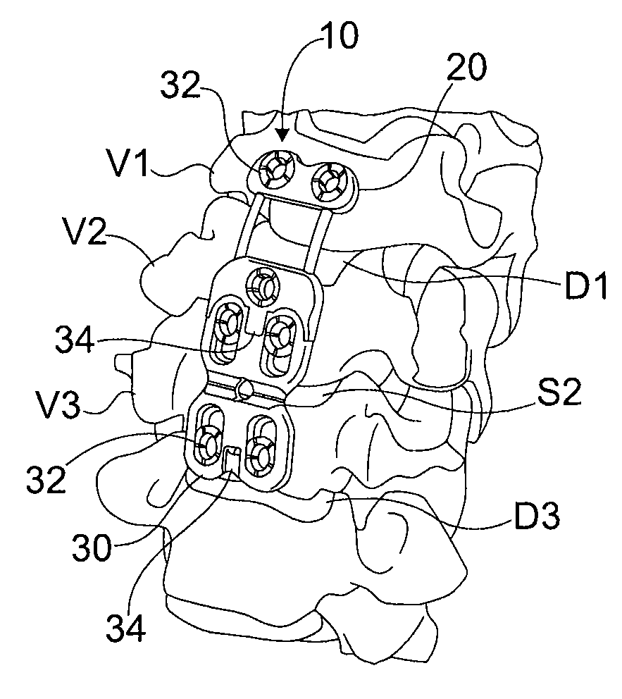
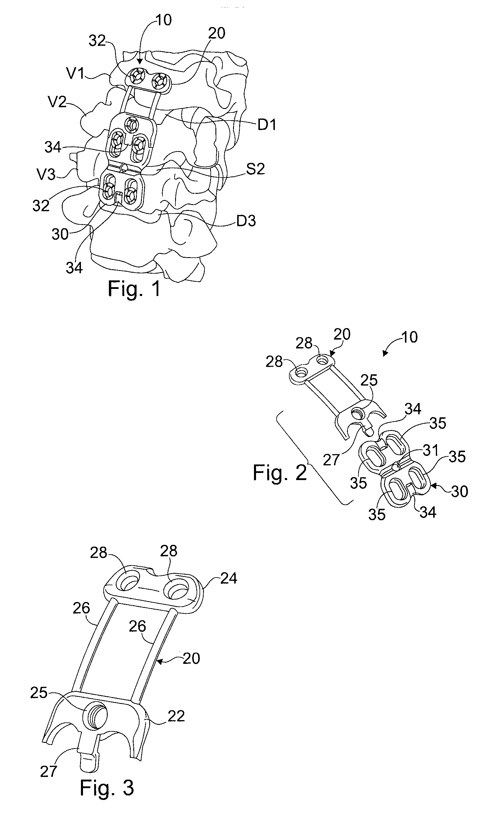
[0029]The problems associated with spinal surgery and revision procedures are resolved in several respects by osteosynthetic plate assemblies and procedures for using the assemblies, all in accordance with the present invention. The applicants generally propose to protect discs that lie in proximity to fusion sites (“neighboring discs”) from accelerated degeneration by controlling the kinematics of those discs. The mobility of the neighboring discs is controlled without resorting to further fusion, which would sacrifice all mobility at those disc sites. Controlling the kinematics of neighboring discs protects the neighboring discs from damage caused by increased s...


PUM


Abstract

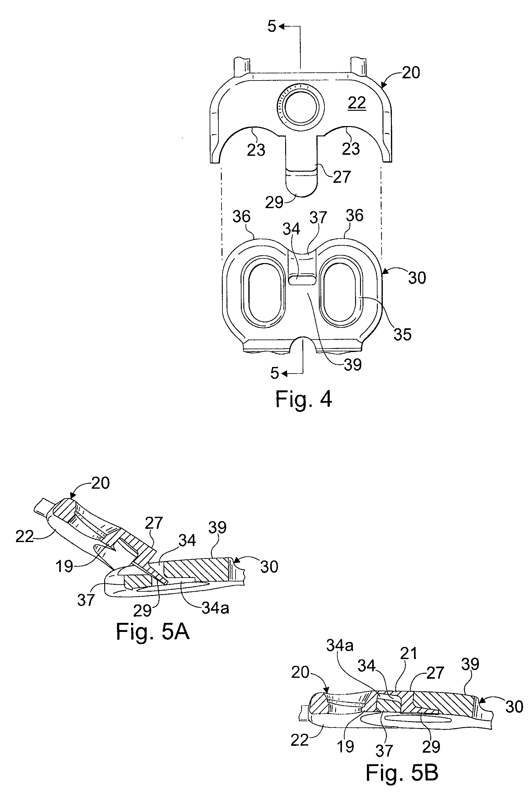
An osteosynthetic plate assembly and a method of installing the osteosynthetic plate assembly is disclosed. The osteosynthetic plate assembly comprises a dynamic extension plate having a first end portion for connection to a first vertebrae, a second end portion for connection to a second vertebrae, and a dynamic flexible portion extending between the first and second end portions. The dynamic extension plate is configured for coupling with a cervical fusion plate. A method of installing the dynamic extension plate to adjacent vertebrae comprises the steps of engaging a connector of the dynamic extension plate with a coupling of a cervical fusion plate, and mounting the dynamic extension plate to the adjacent vertebrae.

Description

FIELD OF THE INVENTION[0001]The present invention relates generally to controlling kinematics of the body, and more specifically to a dynamic extension for an implant, and a method for installing a dynamic extension to an implant to control the kinematics of areas adjacent to the implant.BACKGROUND OF THE INVENTION[0002]Anterior cervical discectomy and fusion (ACDF) is a common surgical procedure for treating nerve root or spinal cord compression caused by a degenerated or herniated disc. In the course of an ACDF procedure, the surgeon enters the intervertebral space and removes all or a portion of a degenerated disc. The intervertebral space is then filled with bone graft. The graft is intended to accelerate the biological fusion of adjacent vertebrae. The bone graft may be an autograft, allograft, synthetic bone substitute, or bone morphogenic protein (BMP). Alternatively, a spacer having a hollow center that is pre-filled with bone graft may be positioned in the intervertebral sp...

Claims


Application Information

Patent Timeline
IPC IPC(8): A61B17/70A61B17/58A61B19/00A61F2/44
CPCA61B17/7059A61B17/8023A61F2002/30578A61F2/442A61F2002/30565A61B2017/00867
Inventor TYBER, JEFFREYWING, CHARLESHALLECK, ROBERTCOLE, JEFF
Owner AESCULAP INC
Why Eureka
Eureka Blog
Learn More