Parts Assembly and Part for a Prosthesis

a technology of parts and prostheses, applied in the field of parts assembly and parts of a prosthesis, can solve the problems of loss of function of the affected vertebral motor segment, widespread clinical use, and promote the degeneration of these connecting segments, and achieve the effect of cost-effective and low manufacturing complexity

Inactive Publication Date: 2009-02-12
MEISEL HANS JORG
View PDF20 Cites 18 Cited by
  • Summary
  • Abstract
  • Description
  • Claims
  • Application Information

AI Technical Summary

Benefits of technology

[0006]It an object of the invention to provide an improved parts assembly and an improved part for a prosthesis, which are cost-effective and can be manufactured with as little complexity as possible.

Problems solved by technology

To date, this operative procedure has of course been associated with a loss of function of the affected vertebral motor segment.
This has the disadvantage that the connecting vertebral motor segments are worse affected than before by the lifting effect of the fused vertebrae obtained after fusion, which promotes increasing degeneration in these connecting segments.
Developments proposed to date for cervical spine intervertebral disc prostheses, which have led to market-ready products, are not very widely used in terms of clinical use since complicated operational procedures are required to implant them and these are associated with irreversible changes to the lower end plate and upper end plate of the affected vertebral bodies.
The reason for the high size of this implant is the very complex structure, which performs a shock-absorbing function, and also the fact that the structure is composed of a large number of individual parts, which are made of different materials.
Implantation takes a great deal of time and requires the use of more than 30 implantation instruments.

Method used


Image

  • Parts Assembly and Part for a Prosthesis
  • Parts Assembly and Part for a Prosthesis
  • Parts Assembly and Part for a Prosthesis

Examples


Embodiment Construction

[0018]The invention will be explained in more detail below on the basis of preferred embodiments and with reference to a drawing, in which:

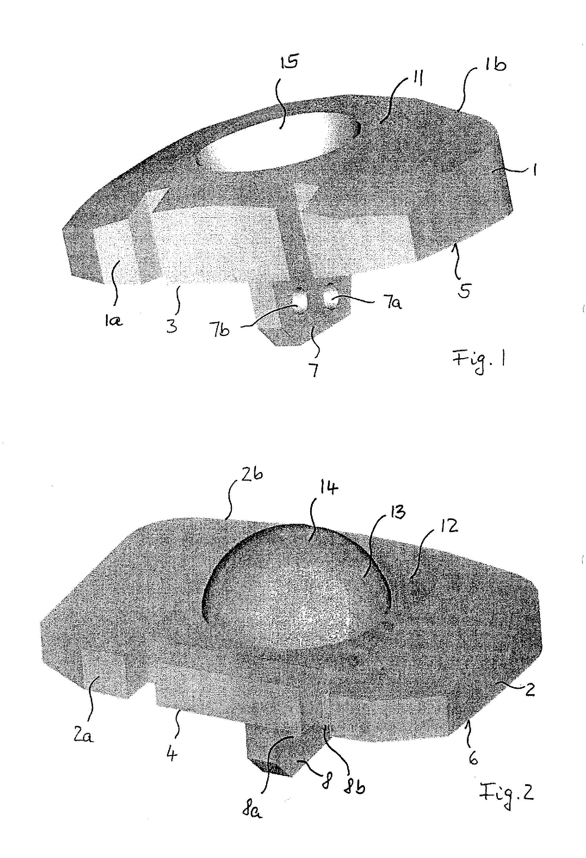
[0019]FIG. 1 shows a perspective view of a base part for a parts assembly for use as a prosthesis;

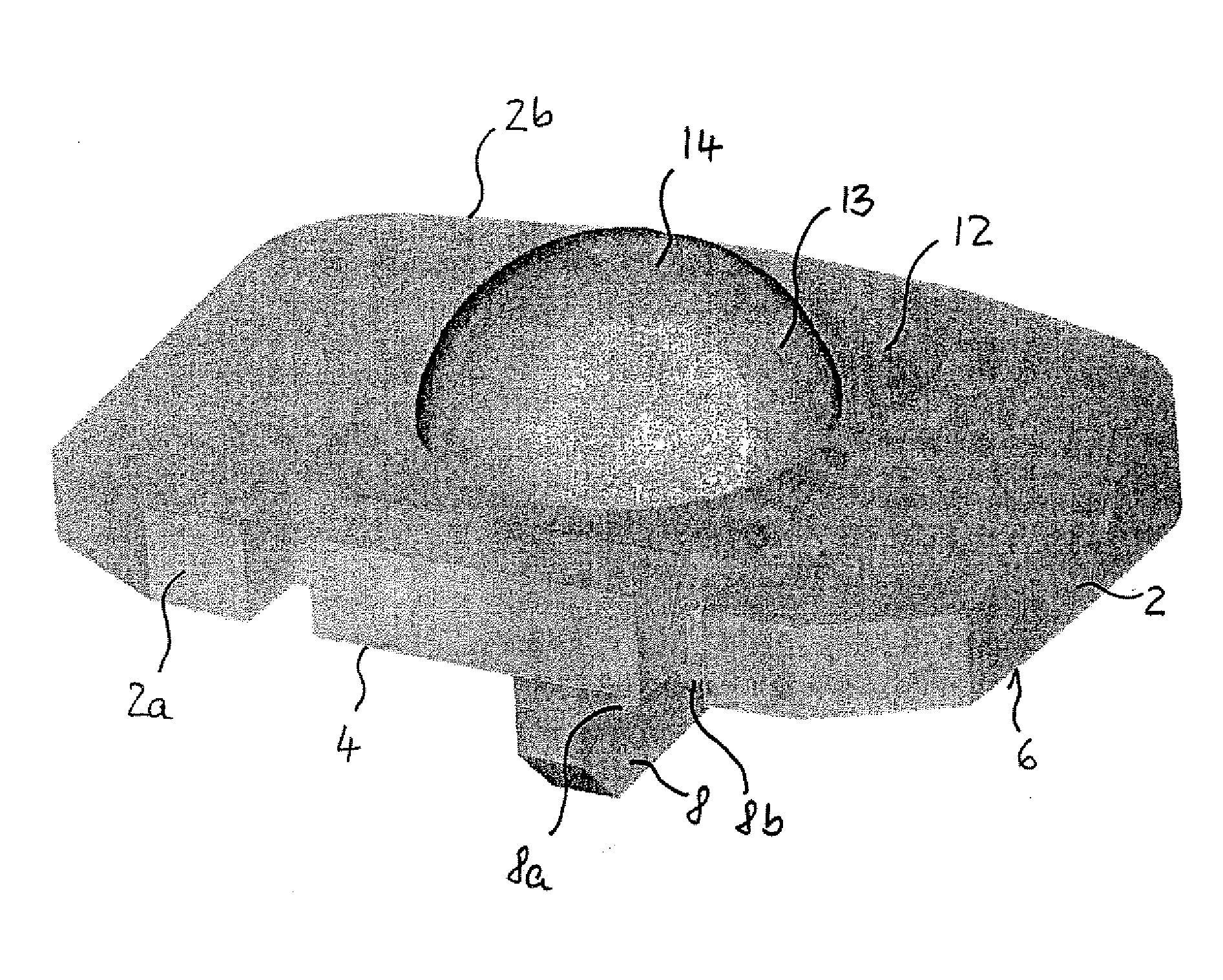
[0020]FIG. 2 shows a perspective view of a further base part for a parts assembly, together with the base part of FIG. 1, for use as a prosthesis;

[0021]FIG. 3 shows a perspective view of a parts assembly comprising the base part of FIG. 1 and the further base part of FIG. 2 in the coupled state;

[0022]FIGS. 4A and 4B show a view of two bone parts, which are joined by means of a parts assembly according to FIG. 3, in a coupled and decoupled state; and

[0023]FIGS. 5A and 5B show a view of two further bone parts, which are joined by means of a parts assembly according to FIG. 3, in a coupled and decoupled state.

[0024]FIGS. 1 and 2 show a perspective view of a base part 1 and of a further base part 2 for a parts assembly for use as a prosthesis, particular...


PUM

PropertyMeasurementUnit
contact surfaceaaaaaaaaaa
pressureaaaaaaaaaa
heightaaaaaaaaaa

Abstract

The invention relates to a parts assembly for a prosthesis, particularly a cervical spine intervertebral disc prosthesis, comprising two base parts (1, 2), which are coupled to one another in an articulated manner by means of coupling parts (11, 12) formed on said base parts. These base parts, together with an associated coupling part, are provided as a single piece. The base parts and the coupling parts are made of one material, which is selected from the following group of materials: polyetherketone (PEK) polyetheretherketone (PEEK), polyacryletherketone (PAEK), polyetherketoneketone (PEKK), polyetherketoneetherketoneketone (PEKEKK) and polyetherketoneetherketone (PEKEK).

Description

[0001]The invention relates to a parts assembly and to a part for a prosthesis, particularly a cervical spine intervertebral disc prosthesis.BACKGROUND OF THE INVENTION[0002]Prostheses based on one or more parts are used to support the functionality of, or even replace, parts of the bone skeleton, for example the spine or a joint.[0003]Degenerative damage to the cervical spine which is associated with a herniated disc or compresses the spinal cord as a result of bone constriction is usually operated on ventrally when an operation is required. When operating in this way, the cervical disc usually has to be completely removed in order to relieve the pressure on the spinal cord and the nerve root. To date, this operative procedure has of course been associated with a loss of function of the affected vertebral motor segment. In order to prevent an additional loss of height of the disc, which can lead to an increase in degenerative and neurological changes, the ventral fusion operation h...

Claims


Application Information

Patent Timeline
Patent Type & Authority Applications(United States)
IPC IPC(8): A61F2/44A61F2/00A61F2/02A61F2/30
CPCA61F2/4425A61F2002/305A61F2002/30556A61F2002/30563A61F2002/30578A61F2002/30604A61F2310/00796A61F2002/30649A61F2002/30884A61F2002/443A61F2220/0025A61F2250/0009A61F2310/00029A61F2002/30616
Inventor MEISEL, HANS JORG
Owner MEISEL HANS JORG
Why Eureka
Try Eureka