Motor Vehicle and Control Method of Motor Vehicle

a technology of motor vehicles and control methods, applied in special data processing applications, gas pressure propulsion mountings, combustion air/fuel air treatment, etc., can solve problems such as electrical energy insufficiency, and achieve the effect of preventing electrical energy insufficiency

Active Publication Date: 2009-02-12
TOYOTA JIDOSHA KK
View PDF9 Cites 27 Cited by
  • Summary
  • Abstract
  • Description
  • Claims
  • Application Information

AI Technical Summary

Benefits of technology

[0004]An object of the invention is to eliminate the drawbacks of the prior art technique and to provide a motor vehicle that prevents an insufficiency of electrical energy by regulation of an internal pressure of a fuel tank, as well as a corresponding control method of such a motor vehicle.
[0007]The motor vehicle of the invention controls the regulation of the internal pressure of the fuel tank, based on the measured state of charge of the accumulator unit on the start of or in the course of the regulation of the internal pressure of the fuel tank. This arrangement effectively prevents an insufficiency of electrical energy caused by the regulation of the internal pressure of the fuel tank.
[0010]The motor vehicle of the invention controls the regulation of the internal pressure of the fuel tank and the charging of the accumulator unit, based on the measured state of charge of the accumulator unit on the start of or in the course of the regulation of the internal pressure of the fuel tank. This arrangement charges the accumulator unit in a low state of charge and thus effectively prevents an insufficiency of electrical energy. The charging system may be a high-voltage power source used to drive the motor vehicle, and the accumulator unit may be a low-voltage power source.
[0012]In another preferable embodiment of the motor vehicle of the invention, the pressure regulation control module controls the pressure regulation by the pressure regulation mechanism, in order to apply a negative pressure into the fuel tank at a time of supply of the fuel to the fuel tank. This arrangement effectively prevents an insufficiency of electrical energy caused by the regulation of the internal pressure of the fuel tank during fueling for fuel vapor treatment in the fuel tank.
[0013]In still another preferable embodiment of the motor vehicle of the invention, the pressure regulation control module controls the pressure regulation by the pressure regulation mechanism, in order to apply a negative pressure into the fuel tank when the motor vehicle stops in an undrivable state for a preset long time period. This arrangement effectively prevents an insufficiency of electrical energy caused by the regulation of the internal pressure of the fuel tank for leak diagnosis, which specifies the presence or the absence of any leak of the fuel vapor in the fuel tank or in a relevant system, when the preset long time period has elapsed since a stop of the motor vehicle. The long time period is determined empirically as a time required for stabilizing the internal pressure of the fuel tank after a stop of the motor vehicle and may be set in a range of 3 to 7 hours.
[0016]The control method of the invention controls the regulation of the internal pressure of the fuel tank, based on the measured state of charge of the accumulator unit on the start of or in the course of the regulation of the internal pressure of the fuel tank. This arrangement effectively prevents an insufficiency of electrical energy caused by the regulation of the internal pressure of the fuel tank. The control method may further include the steps for realizing respective functions of the motor vehicle of the invention described above.

Problems solved by technology

Continuation of the fuel vapor treatment and the leak diagnosis in a low state of charge of the accumulator unit may cause an insufficiency of electrical energy and interfere with a start of another required operation of the hybrid vehicle with a supply of electrical energy from the accumulator unit.

Method used


Image

  • Motor Vehicle and Control Method of Motor Vehicle
  • Motor Vehicle and Control Method of Motor Vehicle
  • Motor Vehicle and Control Method of Motor Vehicle

Examples


Embodiment Construction

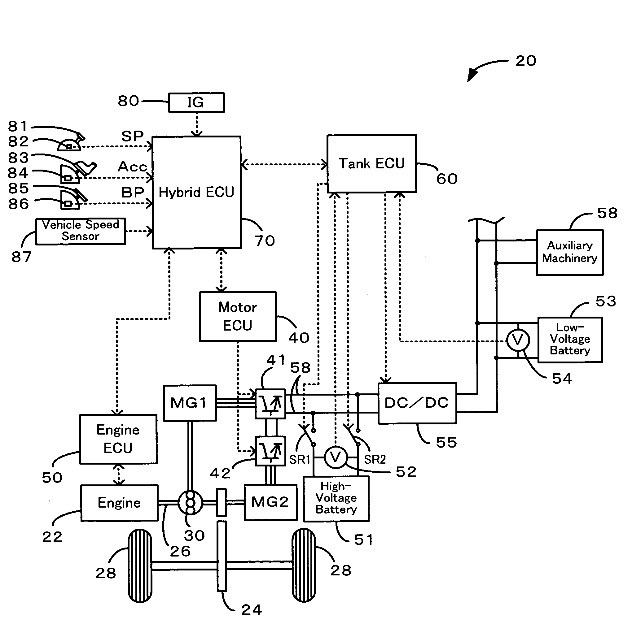
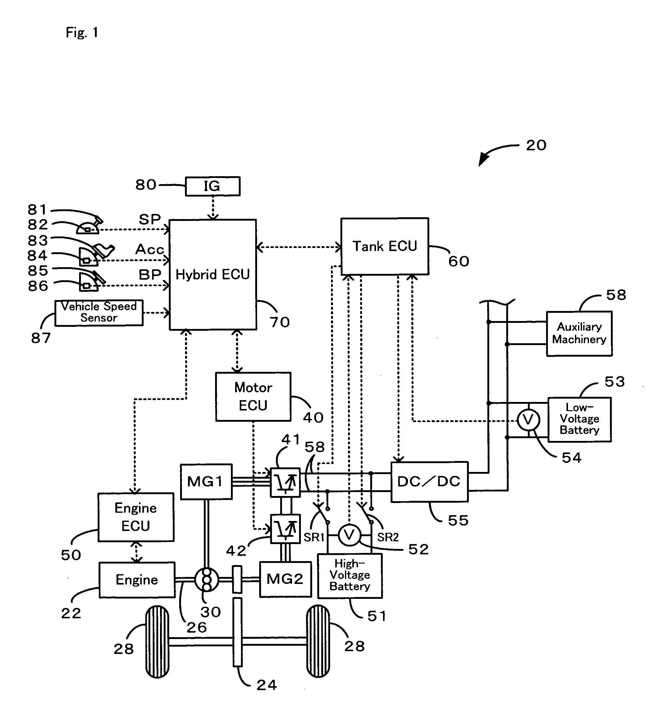
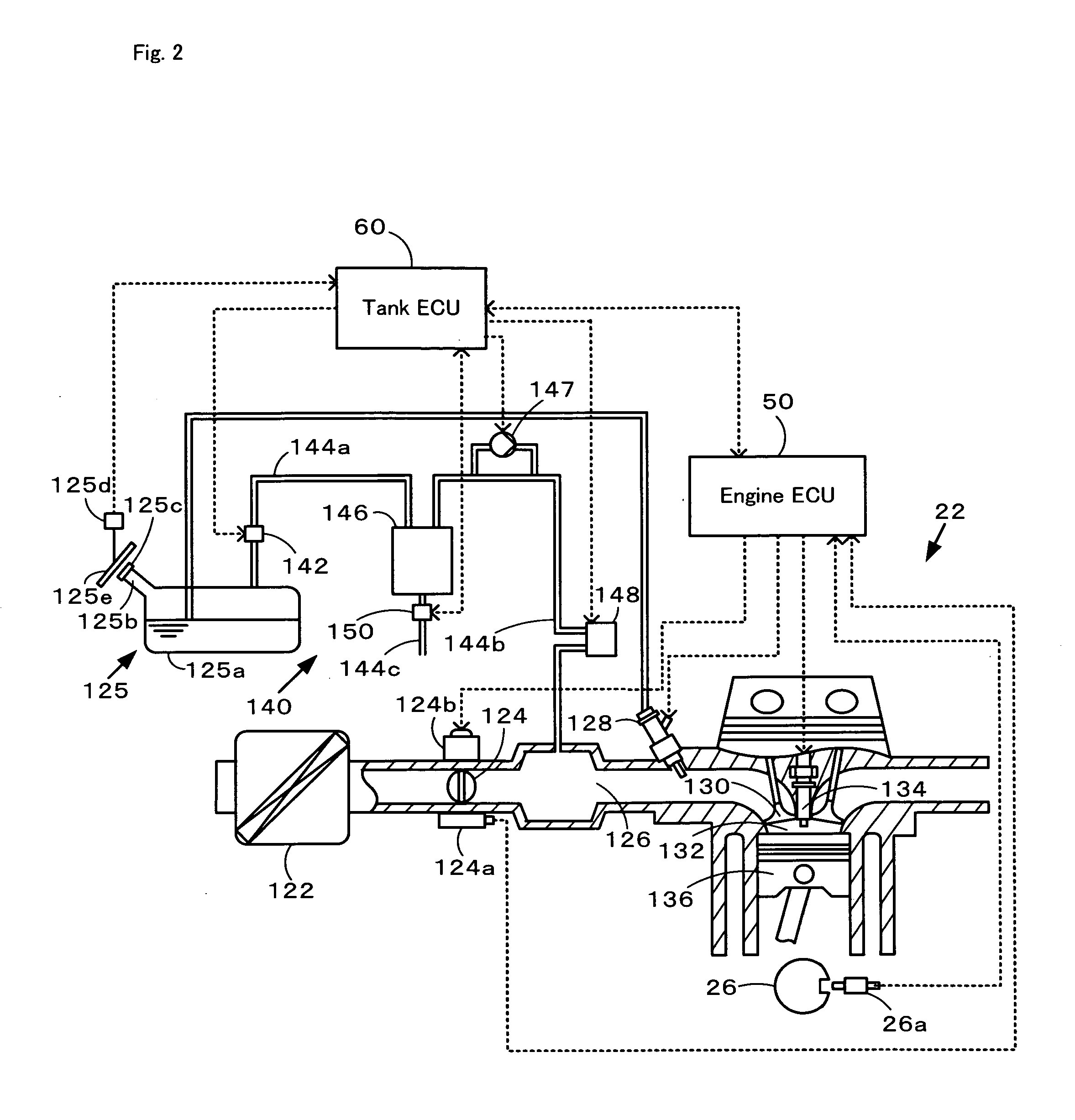
[0028]One mode of carrying out the invention is described below as a preferred embodiment with reference to the accompanied drawings. FIG. 1 schematically illustrates the configuration of a hybrid vehicle 20 in one embodiment of the invention. FIG. 2 schematically shows the structure of an engine 22 mounted on the hybrid vehicle 20 of the embodiment. As illustrated in FIG. 1, the hybrid vehicle 20 of the embodiment includes an engine 22 that is driven with gasoline as a fuel, a three shaft-type power distribution integration mechanism 30 that is connected to a crankshaft 26 or an output shaft of the engine 22, motors MG1 and MG2 that are linked to the power distribution integration mechanism 30 and have power generation capability, a high-voltage battery 51 that transmits electrical energy to and from the motors MG1 and MG2, a low-voltage battery 53 that transmits electrical energy to and from the high-voltage battery 51, an engine electronic control unit 50 (hereafter referred to a...


PUM


Abstract

In a hybrid vehicle of the invention, when a voltage level E of a low-voltage battery exceeds a preset alert reference value Eth1 (step S115), fueling control activates a negative pressure pump with a preset amount of power consumption for standard fuel vapor treatment (step S125). When the voltage level E of the low-voltage battery exceeds a low charge reference value Elow but is not higher than the preset alert reference value Eth1 (steps S115 and S120), the fueling control activates the negative pressure pump with a smaller amount of power consumption (step S130). When the voltage level E of the low-voltage battery is not higher than the low charge reference value Elow (step S120), the fueling control inactivates the negative pressure pump (step S135). Such control enables at least a voltage of the low charge reference value Elow to be reserved in the low-voltage battery even after regulation of internal pressure of a fuel tank. This effectively prevents an insufficiency of electrical energy by the regulation of the internal pressure of the fuel tank.

Description

TECHNICAL FIELD[0001]The present invention relates to a motor vehicle and a control method of the motor vehicle. More specifically the invention pertains to a motor vehicle having a pressure regulating function in a fuel tank, as well as to a control method of such a motor vehicle.BACKGROUND ART[0002]A prior art motor vehicle is equipped with a fuel vapor treatment system that causes fuel vapor generated in a fuel tank to be adsorbed and temporarily kept on a canister and supplies the adsorbed fuel vapor into an air intake system of an internal combustion engine to be burned out by the internal combustion engine. A proposed structure of the fuel vapor treatment system includes a sealing valve located between the fuel tank and the canister and a pump located between the canister and the air intake system of the internal combustion engine. For example, a known fuel vapor treatment system disclosed in Japanese Patent Laid-Open Gazette No. 2004-156492 opens the sealing valve during fuel...

Claims


Application Information

Patent Timeline
Patent Type & Authority Applications(United States)
IPC IPC(8): F02D45/00B60K6/28B60K6/445B60K15/035B60K15/077B60W10/26B60W10/30B60W20/00F02M25/08F02M37/08
CPCB60W10/26B60W10/30F02M25/0809F02D41/003B60W20/00B60W20/13
Inventor SAITO, KIMIOTANAKA, NOBUYUKI
Owner TOYOTA JIDOSHA KK
Why Eureka
Try Eureka