

Drums for hogging apparatus
- Summary
- Abstract
- Description
- Claims
- Application Information
AI Technical Summary
Benefits of technology
Problems solved by technology
Method used
Image

Examples
Embodiment Construction
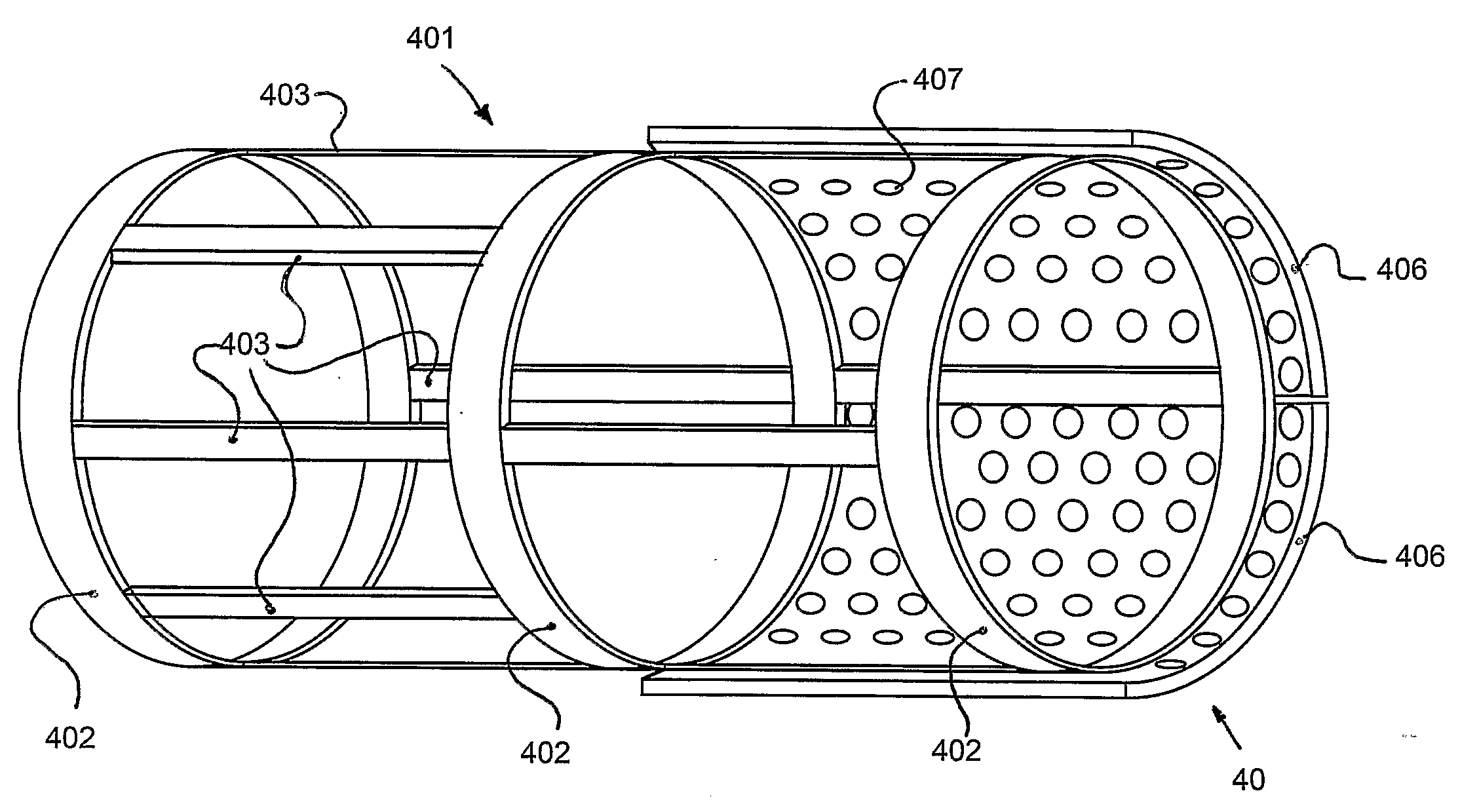
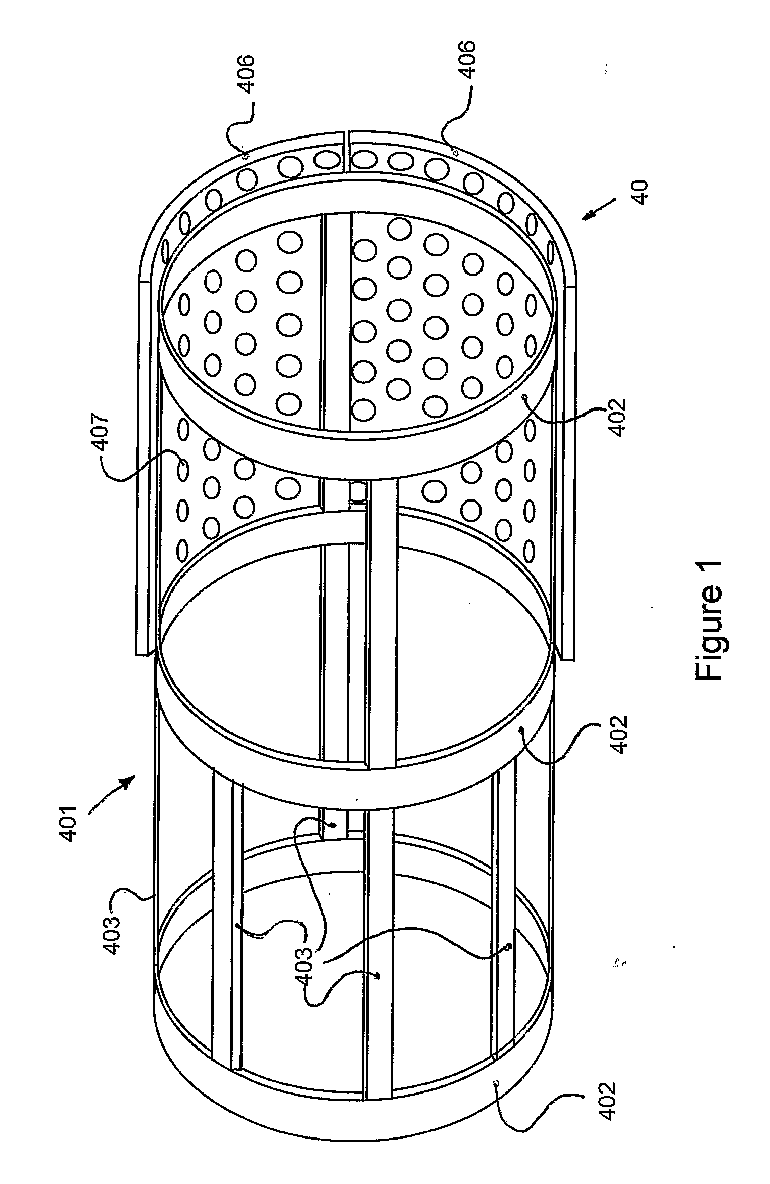
[0121]With reference to the drawings and by way of example only there is provided a drum arrangement for use in reducing apparatus. This comprises a paddle arrangement (generally indicated by arrow 401). The paddle arrangement is substantially an open framework made up of a plurality of circumferential elements (402) and longitudinal elements (403) though only some are shown for clarity in the drawing. The paddle arrangement is driven and rotates relative to the drum (40). The drum (40) comprises a substantially similar framework (not visible) to that of the paddle arrangement (401). However, here the elements of the frame support screening plates (406) with screening apertures (407) therein. These plates (406) are removable and typically of a steel material.
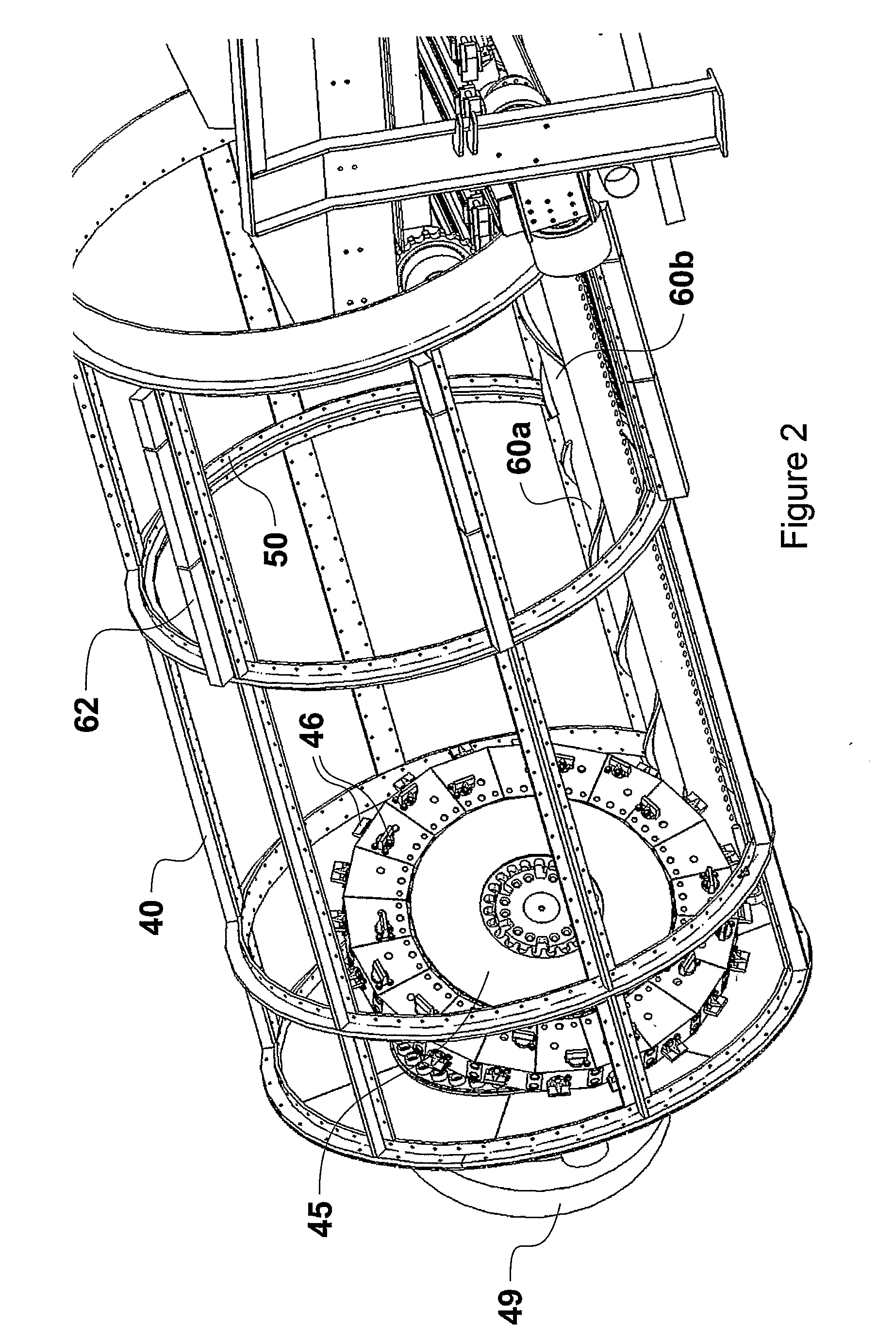
[0122]Reducing apparatus employing the drum arrangement of FIG. 1 is illustrated in FIG. 2, though here only the drum (40) with screening plates removed is shown for clarity. The paddle arrangement can have a very similar struct...
PUM
 Abstract
Description
Claims
Application Information