Magnetic integrated circuit for multiphase interleaved flyback converter and controlling method thereof

Active Publication Date: 2009-02-19
DELTA ELECTRONICS INC
View PDF4 Cites 60 Cited by
  • Summary
  • Abstract
  • Description
  • Claims
  • Application Information

AI Technical Summary

Benefits of technology

[0006]It is therefore an object of the present invention to provide a multiphase interleaved flyback converter and a controlling method thereof to further enhance the original functions of the interleaved flyback converter and to increase the power level

Problems solved by technology

But the aforementioned flyback converter has the disadvantages: the energy transmission capability is inferior, the input/output ripples are relatively larger, the utilization ratio of magnetic core is low, and the winding loss is larger (especially the transformer's air gap fringing loss), thus the flyback converter is not preferred in the high power applications.
When the trend

Method used


Image

  • Magnetic integrated circuit for multiphase interleaved flyback converter and controlling method thereof
  • Magnetic integrated circuit for multiphase interleaved flyback converter and controlling method thereof
  • Magnetic integrated circuit for multiphase interleaved flyback converter and controlling method thereof

Examples


Example

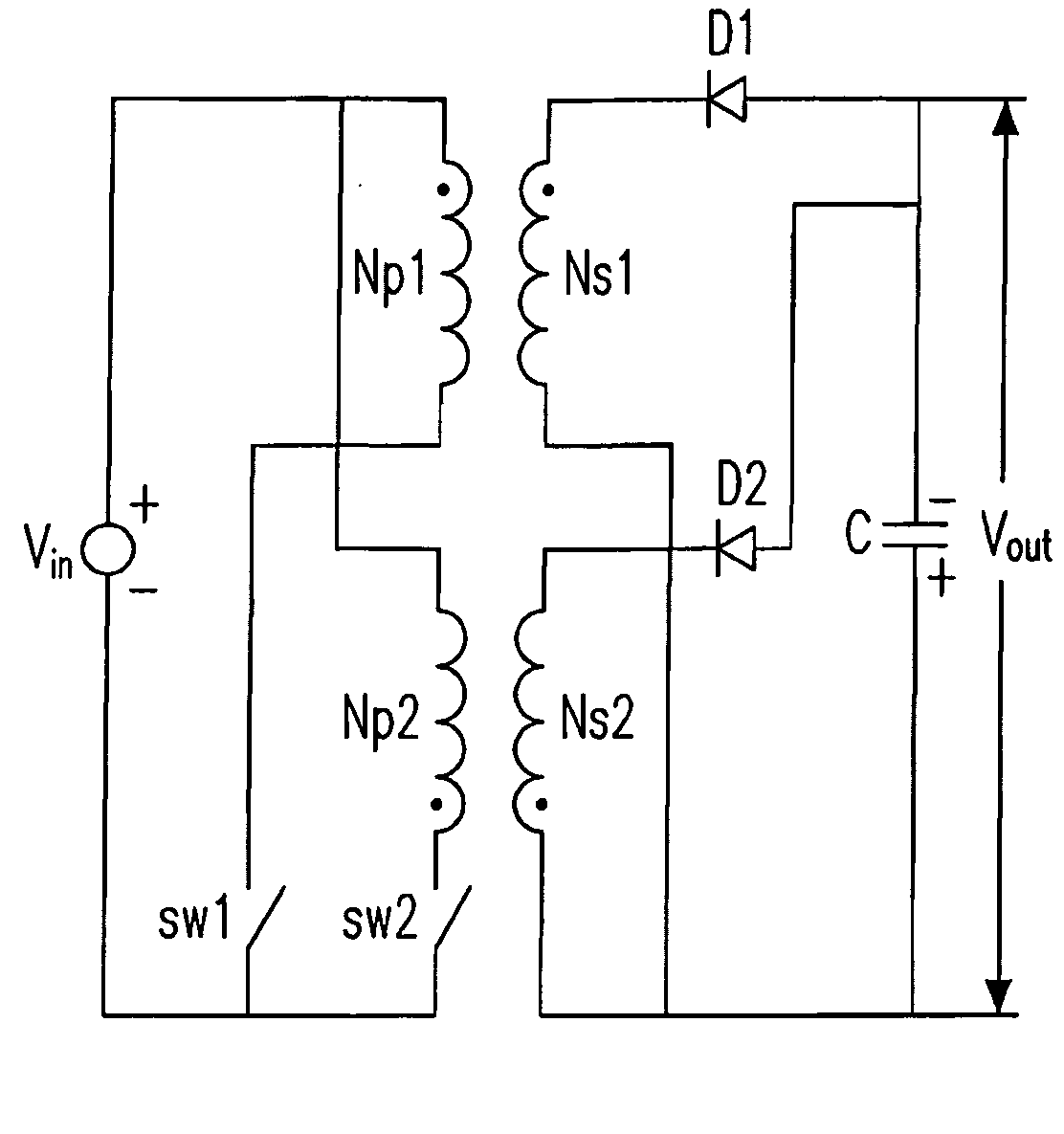
[0047]Please refer to FIG. 4(a), which shows a circuit diagram of a two-phase interleaved flyback converter according to the first preferred embodiment of the present invention. Which shows a first primary winding Np1 and a first secondary winding Ns1 of a transformer (not shown), and the first terminals of windings Np1 and Ns1 have the same polarity; a second primary winding Np2 and a second secondary winding Ns2, and the second terminals of windings Np2 and Ns2 also have the same polarity as that of the first terminal of the first primary winding Np1 such that the current ripples on each channel are eliminated; it further includes a first switch SW1, a second switch SW2, a first diode D1, a second diode D2 and an output capacitor C, and the converter is employed to receive a DC input voltage Vin and generate an output voltage Vout.

[0048]FIG. 4(b) shows a schematic circuit diagram of the two-phase interleaved flyback converter according to the first preferred embodiment of the pres...


PUM


Abstract

The configurations of an interleaved flyback converter and a controlling method thereof are provided. The proposed two-phase interleaved flyback converter includes a transformer including a first primary winding having a first terminal, a first secondary winding having a first terminal, a second primary winding having a second terminal, a second secondary winding having a second terminal and a magnetic coupled core device, wherein the first primary, the first secondary, the second primary and the second secondary windings are wound therein, and the first terminal of the first primary winding has a polarity the same as that of any of the first terminal of the first secondary winding, the second terminal of the second primary winding and the second terminal of the second secondary winding so as to eliminate a ripple of a channel current of the converter.

Description

FIELD OF THE INVENTION[0001]The present invention relates to a magnetic integrated circuit of a two-phase interleaved flyback converter and a controlling method of a multiphase interleaved flyback converter. More particularly, the present invention relates to a multiphase interleaved flyback converter having a transformer with a plurality of primary windings and a plurality of secondary windings.BACKGROUND OF THE INVENTION[0002]Flyback converters relatively posses the advantages of having simple configuration and lower costs, and have been broadly applied to the apparatuses such as adapters etc. As shown in FIG. 1(a), it is a circuit diagram of a flyback converter in the prior art. In which, the flyback converter includes a transformer T, a switch SW, a diode D and an output capacitor C receiving a DC input voltage Vin and an output voltage Vout. FIG. 1(b) shows a schematic circuit diagram of a flyback converter having a magnetic core (mc) in the prior art. In which, the magnetic co...

Claims


Application Information

Patent Timeline
IPC IPC(8): H02M1/14
CPCH02M3/285H01F27/385
Inventor LU, ZENGYICHEN, WEIPENG, MING HSIEN
Owner DELTA ELECTRONICS INC
Why Eureka
Try Eureka