Igbt/fet-based energy savings device, system and method

a technology of energy saving device and field effect transistor, which is applied in the direction of electric variable regulation, process and machine control, instruments, etc., can solve the problems of wide disparity of voltages available to consumers in homes, inability to maintain nominal ac voltage, and rapid increase in the cost of such resources

Active Publication Date: 2009-02-19
THE POWERWISE GRP
View PDF99 Cites 43 Cited by
  • Summary
  • Abstract
  • Description
  • Claims
  • Application Information

AI Technical Summary

Benefits of technology

[0009]The primary object of the present invention is to provide an IGBT / FET-based device, system and method wherein a predetermined amount of voltage below a nominal line voltage is saved, thereby conserving energy.
[0010]Another object of the present invention is to provide an IGBT / FET-based device, system and method wherein a predetermined amount of voltage below a nominal appliance voltage is saved, thereby conserving energy.

Problems solved by technology

As the depletion of Earth's natural resources continues, power generation and energy conservation has become an increasingly important issue with governments in both this country and abroad.
In addition, not only are governments concerned with power generation and energy conservation, but businesses and consumers are also concerned as the costs for such resources are rapidly increasing.
Although power generation and energy conservation are of great importance, the problem of power distribution is also of great concern as it involves existing infrastructure that is usually inadequate for properly distributing power and not readily suitable to be improved upon.
This problematical situation is manifested by “brown outs” wherein a nominal AC voltage cannot be maintained in the face of a grid / generation overload.
This method usually results in a wide disparity of voltages available to consumers in homes and / or business.
Furthermore, although most appliances and equipment used in businesses and homes are capable of performing, exactly to specification, at the nominal voltage minus ten percent (10%), most energy savings devices do not exploit this feature.

Method used


Image

  • Igbt/fet-based energy savings device, system and method
  • Igbt/fet-based energy savings device, system and method
  • Igbt/fet-based energy savings device, system and method

Examples


Embodiment Construction

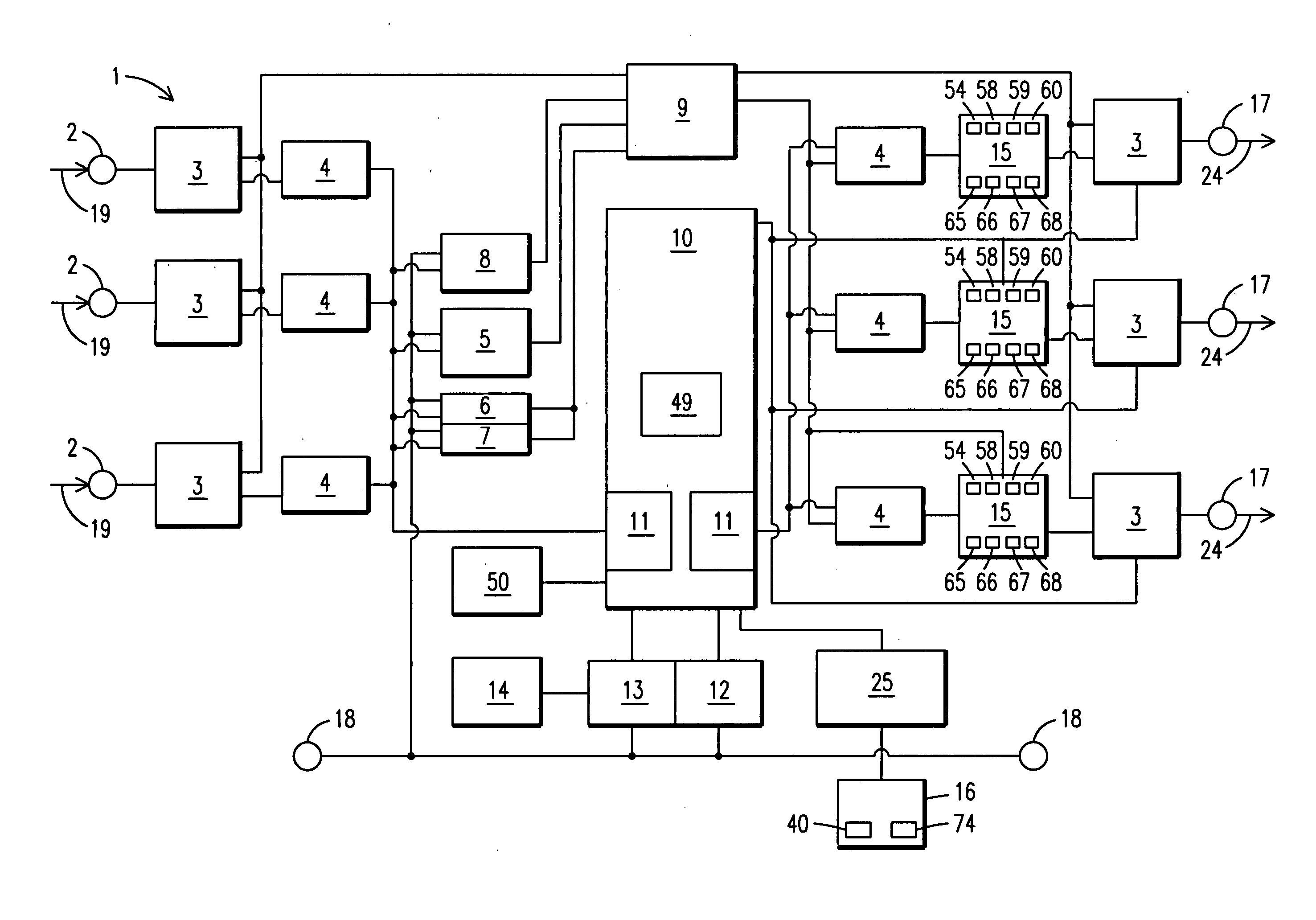
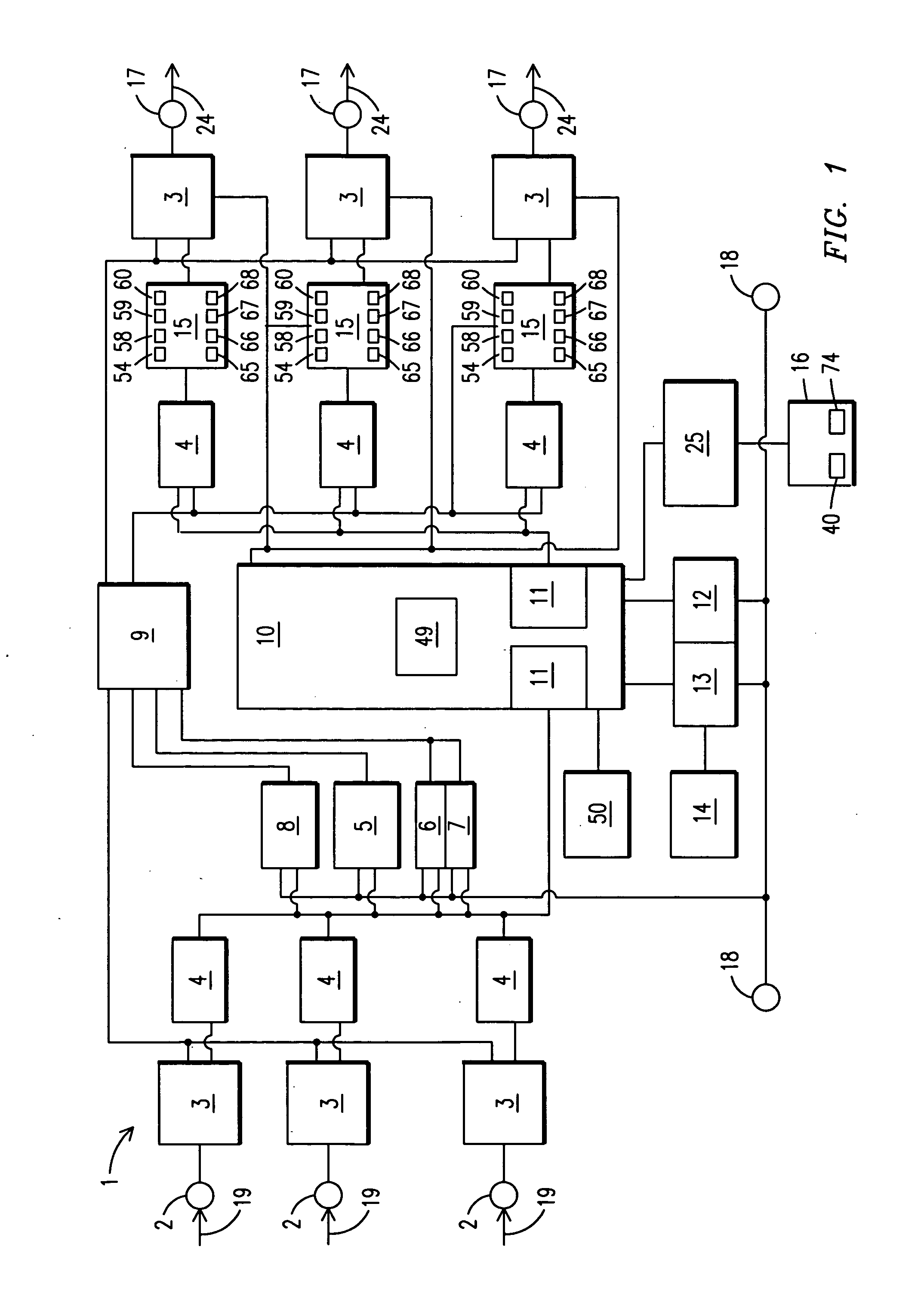
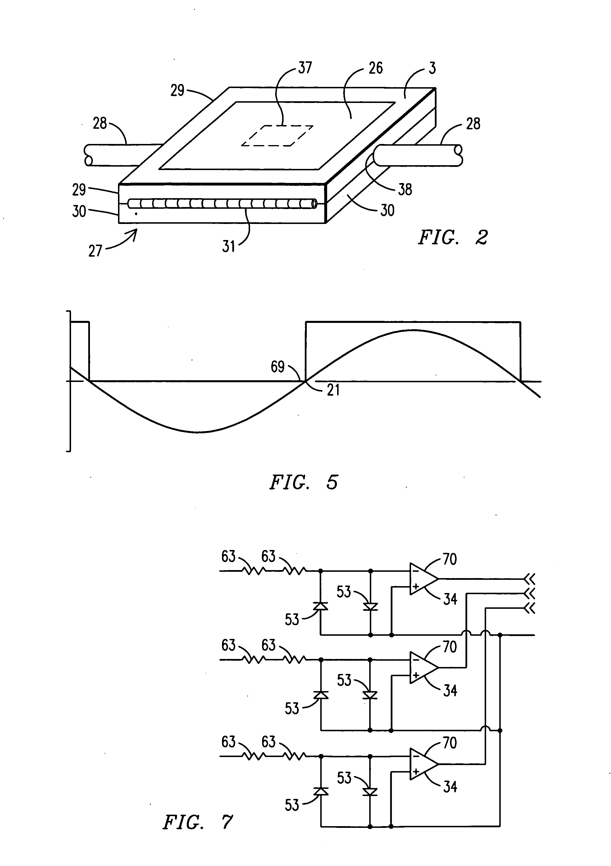
[0062]For purposes of describing the preferred embodiment, the terminology used in reference to the numbered components in the drawings is as follows:[0063]1. IGBT / FET-based energy savings device and system, generally[0064]2. phase input connection[0065]3. magnetic flux concentrator[0066]4. analog signal conditioning device[0067]5. volts zero crossing point detector[0068]6. lost phase detection device[0069]7. phase rotation device[0070]8. half cycle identifier[0071]9. logic device[0072]10. digital signal processor[0073]11. A / D converter[0074]12. power supply unit[0075]13. reset switch[0076]14. light emitting diode[0077]15. IGBT / FET drive control[0078]16. computing device[0079]17. phase output connection[0080]18. neutral[0081]19. incoming energy[0082]20. analog signal[0083]21. volts zero crossing point[0084]22. positive half cycle[0085]23. negative half cycle[0086]24. reduced energy[0087]25. USB communications interface[0088]26. circuit board[0089]27. housing[0090]28. conductor[0091]...


PUM


Abstract

An IGBT / FET-based energy savings device, system and method (1) wherein a predetermined amount of voltage below a nominal line voltage and / or below a nominal appliance voltage is saved, thereby conserving energy. Phase input connections (2) are provided for inputting analog signals into the device and system (1). A magnetic flux concentrator (3) senses the incoming analog signal (20) and a volts zero crossing point detector (5) determines the zero volts crossing point (21) of the signal (20). The positive half cycle (22) and negative half cycle (23) of the signal (20) are identified and routed to a digital signal processor (10) for processing the signal (20). The signal (20) is reduced by pulse width modulation and the reduced amount of energy is outputted, thereby yielding an energy savings for an end user.

Description

CROSS REFERENCE TO RELATED APPLICATION[0001]This application claims the benefit of U.S. Provisional Application Nos. 60 / 964,587 filed Aug. 13, 2007; 60 / 966,124 filed Aug. 24, 2007; 61 / 009,844 filed Jan. 3, 2008; 61 / 009,846 filed Jan. 3, 2008; 61 / 009,845 filed Jan. 3, 2008; and 61 / 009,806 filed Jan. 3, 2008.BACKGROUND OF THE INVENTION[0002]This invention relates to energy savings devices, systems and methods, more particularly, an insulated gate bipolar transistor / field effect transistor (IGBT / FET) based energy savings device, system and method for use wherein a predetermined amount of voltage below a nominal line voltage and / or below a nominal appliance voltage is saved, thereby conserving energy.[0003]Since the industrial revolution, the world's consumption of energy has grown at a steady rate. Most power generated and energy consumed is from the combustion of fossil fuels, a nonrenewable, natural resource that is rapidly becoming depleted. As the depletion of Earth's natural resou...

Claims


Application Information

Patent Timeline
Patent Type & Authority Applications(United States)
IPC IPC(8): H02M5/04
CPCH02M3/158H02M5/293
Inventor LUMSDEN, JOHN L.
Owner THE POWERWISE GRP
Why Eureka
Try Eureka