
Coherent light source

a light source and coherent technology, applied in the direction of instruments, electrical equipment, laser details, etc., can solve the problems of inability to achieve stable generation of shg, material is unsuitable for wavelength conversion elements, and it is difficult to achieve a desired output stably, etc., to achieve stable output characteristics

Inactive Publication Date: 2009-02-19
PANASONIC CORP
View PDF4 Cites 63 Cited by
  • Summary
  • Abstract
  • Description
  • Claims
  • Application Information

AI Technical Summary

Benefits of technology

[0045]The present invention provides a high-power coherent light source in a visible light region using a wavelength conversion element. The coherent light source in accordance with the present invention does not have the problems in output instability at a high output and reliability and has a stable output characteristic.

Problems solved by technology

The reason for this is that it may become difficult to attain a desired output stably if nonlinear materials are subjected to optical damage or the like from an electromagnetic wave, such as the second harmonic, propagating within the wavelength conversion unit and has a high-power.
If using a material having a factor where optical characteristics which is destabilized by receiving light in a wavelength region which includes a wavelength of SHG as a wavelength conversion element, stable generation of SHG cannot be performed.
Such a material is unsuitable for a wavelength conversion element.
In the wavelength conversion element, when the optical damage occurs, a phase matching condition is not satisfied in the portion of the optical damage, resulting in reduction in conversion efficiency of the element.
However, since the optical destruction only occurs at a high power density of light, problems due to this phenomenon do not become obvious when only light having a power density of the level at which the optical destruction does not occur is used.
However, in a coherent light source which a high-power output is required, this problem may become obvious.
Therefore, it is difficult to constitute a light source which produces visible light of high-power using LN, LT or the like.
In short, if we try to construct a configuration of a light source which stably converts visible light of high-power employing LN, LT or the like as a wavelength conversion element, a problem of stability of a light source due to phenomena such as optical damage etc. associated with this configuration will arise.
This phenomenon becomes a factor which limits the power of light to be converted when KTP is used as a wavelength conversion element.

Method used


Image

  • Coherent light source
  • Coherent light source
  • Coherent light source

Examples


first embodiment

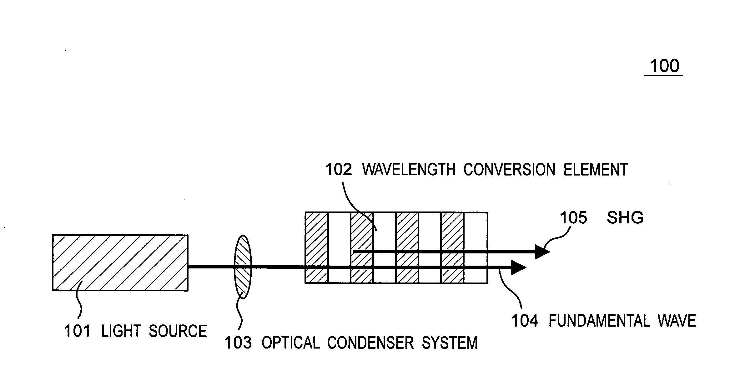
[0134]FIG. 4A is a constitution diagram of a coherent light source 400 in accordance with the first embodiment of the present invention. The coherent light source 400 has a light source 401 composing a light source unit and a wavelength conversion element 402 being a wavelength conversion unit. Further, the coherent light source 400 may include an optical system 403 for condensing light being a light-condensing section in such a way that the optical system 403 for condensing light condenses a fundamental wave 404 exiting the light source 401 to the wavelength conversion element 402. The light source 401 can be pulse-driven by a Q switch in order to improve the efficiency of wavelength conversion by the wavelength conversion element 402. The wavelength conversion element 402 includes PPMgLN of a nonlinear optical material. The fundamental wave 404 exiting the light source 401 is condensed within the wavelength conversion element 402 (PPMgLN) by the optical system 403 for condensing l...

second embodiment

Output Instability Due to Absorption of Visible Light

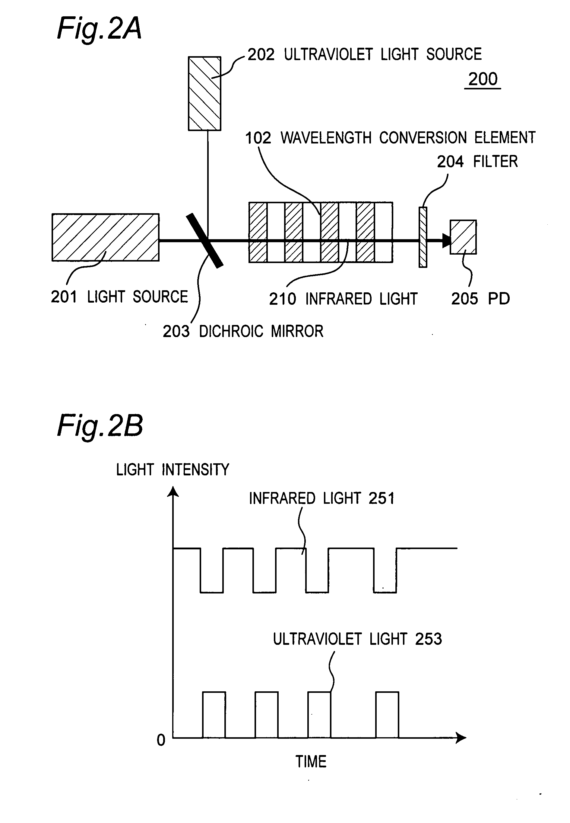
[0167]The above-mentioned output instability due to a thermal lens effect is a phenomenon in which the absorption of the fundamental wave and the harmonics by the wavelength conversion element 402 occurs due to the generation of ultraviolet rays and the thermal lens effect is produced by the absorbed energy and the output is destabilized. When the infrared light is absorbed, an absorption coefficient is relatively small and therefore a power density required for producing the thermal lens effect is high. Therefore, the thermal lens effect is produced by a peak power having a high spiry peak value. On the other hand, an absorption coefficient is large and the thermal lens effect is produced more remarkably for visible light having a short wavelength.

[0168]Further, the absorption also occurs by slight ultraviolet light for light having a wavelength of 600 nm or shorter. Therefore, the absorption of the harmonics occurs by a sum freq...

modification example

[0174]FIG. 9 is a constitution diagram of a wavelength conversion unit 900 in accordance with a modification example of the second embodiment of the present invention. Here, a wavelength conversion element is formed with the normal direction of a stripe of a polarization reversal structure 903 inclined by an angle of theta relative to an optical axis of a fundamental wave 904. Thereby, a walk-off angle theta_W is provided between SHG 905 and the fundamental wave 904 through chromatic dispersion of SHG 905 and the fundamental wave 904. An angle which an optical axis of polarization reversal forms with the fundamental wave 904 is assumed to be a polarization reversal angle. In the case of the constitution shown in FIG. 8, since SHG 805 output is separated into two directions, the decrease in conversion efficiency due to the generation of a walk-off angle of non-zero is relatively large. However, when the wavelength conversion element 902 is constructed as shown in FIG. 9, it is possib...


PUM


Abstract

A coherent light source is provided with a light source unit for projecting a fundamental wave having a first wavelength, and a wavelength converting unit for projecting a second harmonic wave of the fundamental wave at a prescribed average power or more by receiving the fundamental wave. The coherent light source suppresses generation of sum frequency of the second harmonic wave and the fundamental wave, which causes unstable power. Therefore, a constitution is provided for keeping a walk-off angle of the fundamental wave and SFG light at 15 degrees or higher.

Description

TECHNICAL FIELD[0001]The present invention relates to a coherent light source and particularly to a coherent light source including a wavelength conversion element which allows light having a wavelength different from the wavelength of received light to exit by receiving light and converting the wavelength of the light.BACKGROUND ART[0002]With respect to a coherent light source, in recent years, wavelength conversion technology of light has been developed continuously, and consequently a coherent light source becomes highly efficient and high-powered. For example, as a method of realizing a highly efficient coherent light source, there are known a method of improving conversion efficiency of a wavelength by enhancing a power density of a fundamental wave using an internal resonator, and a method of improving conversion efficiency of a wavelength by using a fundamental wave having a high spiry peak value by a Q switch pulse. Both methods realize a highly efficient conversion of about...

Claims


Application Information

Patent Timeline
Patent Type & Authority Applications(United States)
IPC IPC(8): H01S3/10
CPCG02F1/3775
Inventor MIZUUCHI, KIMINORI
Owner PANASONIC CORP
Learn More