

Conditional Scanning
a scanning and conditional technology, applied in the field of conditional scanning, can solve problems such as power consumption
- Summary
- Abstract
- Description
- Claims
- Application Information
AI Technical Summary
Benefits of technology
Problems solved by technology
Method used
Image

Examples
Embodiment Construction
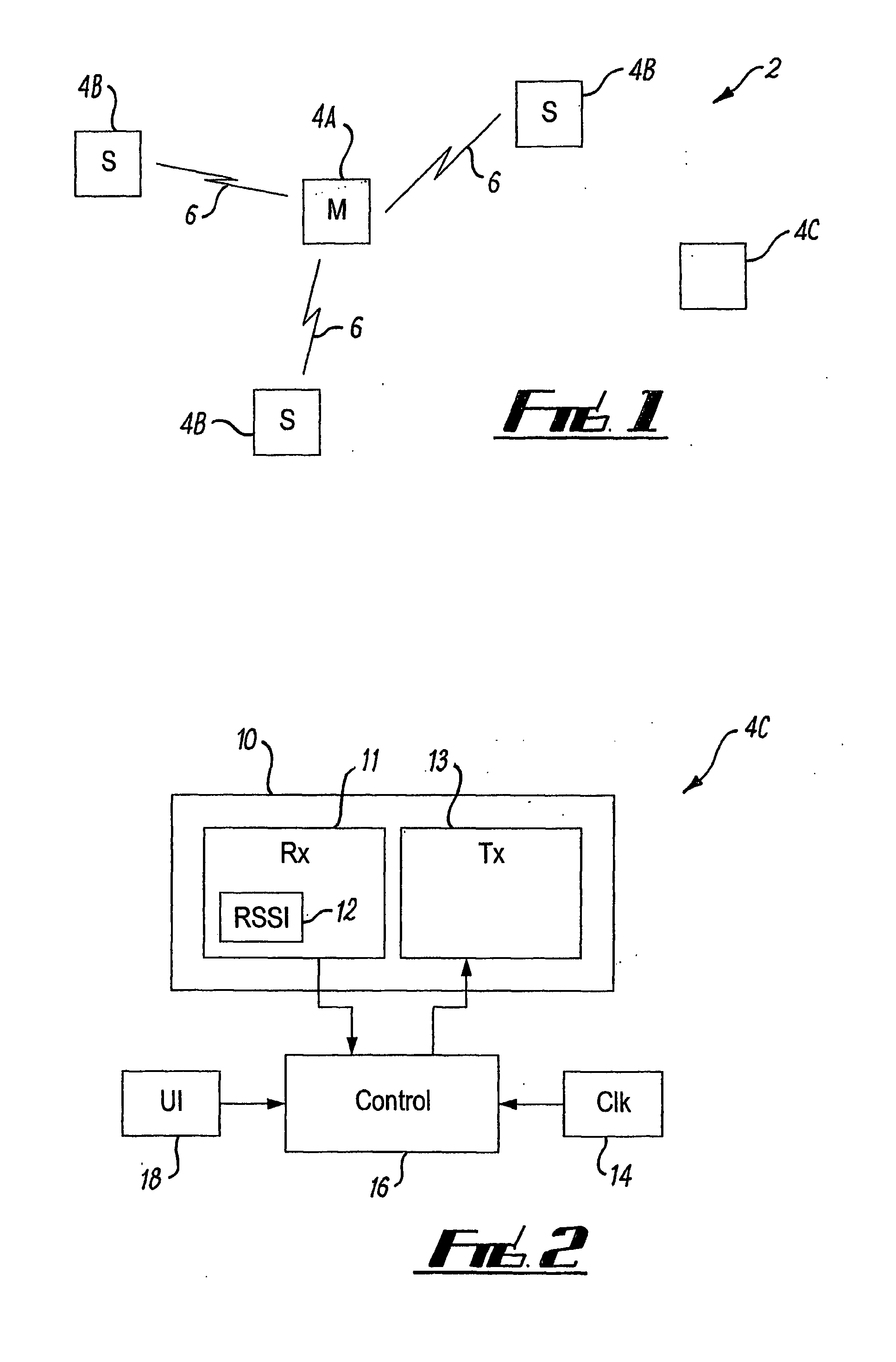
[0041]FIG. 2 illustrates a connectable Bluetooth device 4C that is operable to perform conditional scanning.
[0042]It should be appreciated that although this device is capable of joining and participating in a piconet 2 as a Slave it may also be capable of separately forming a piconet in which it would operate as Master.
[0043]The device 4C comprises radio transceiver circuitry 10 including radio receiver circuitry 11 and radio transmitter circuitry 13; received signal strength indication (RSSI) measurement circuitry 12 associated with the radio receiver circuitry 11; a clock 14; control circuitry 16, which may be, for example, a microprocessor and memory combination or a chip set; and a user input interface 18. The control circuitry 16 receives an input from the receiver circuitry 11& RSSI measurement circuitry 12, an input from the user interface 18 and an input from the clock 14. The control circuitry 16 provides an output to the transmitter circuitry 13.
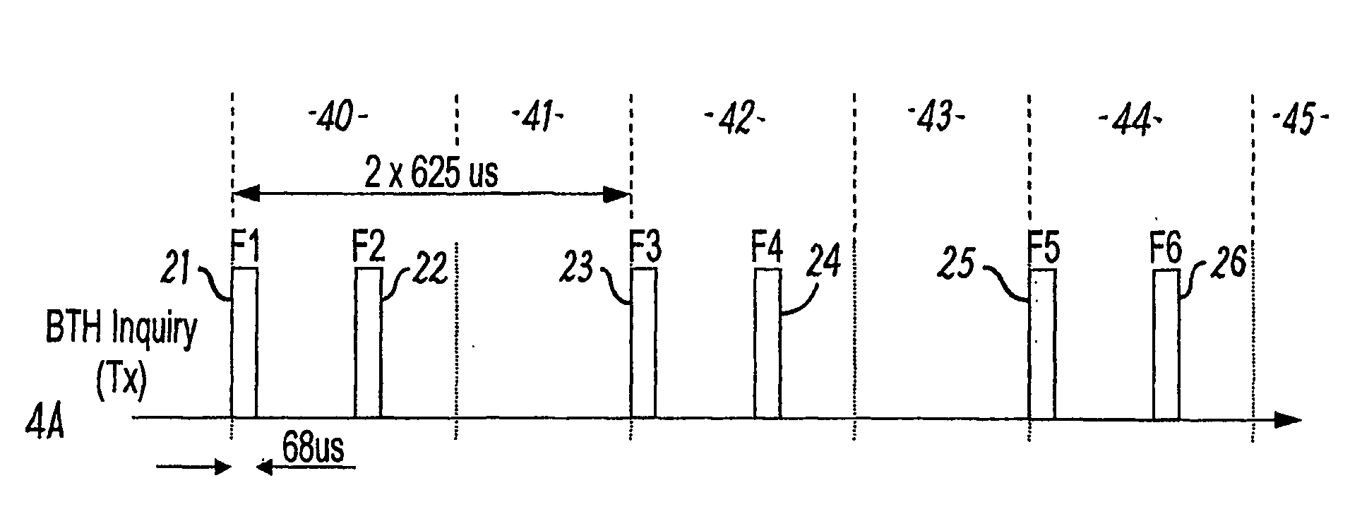
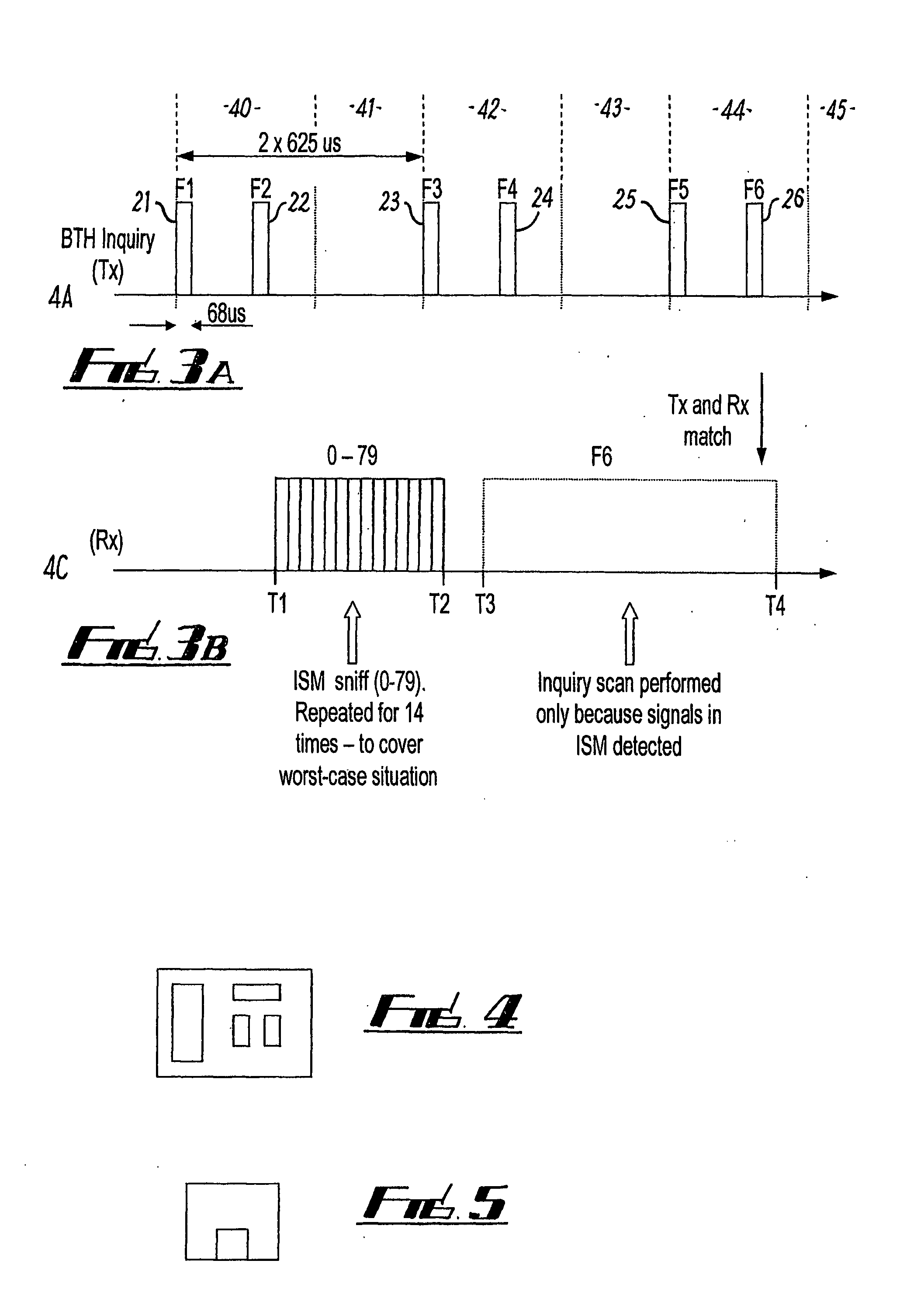
[0044]FIG. 3A illustrates ...
PUM
 Abstract
Description
Claims
Application Information