Multi-mode microwave detection system and method based on fast frequency hopping technology

A microwave detection and frequency hopping technology, used in mode conversion, automatic power control, transmission of sensing components using wave/particle radiation devices, etc.

Active Publication Date: 2022-04-01
JIANGNAN UNIV
View PDF7 Cites 0 Cited by
  • Summary
  • Abstract
  • Description
  • Claims
  • Application Information

AI Technical Summary

Problems solved by technology

But at the same time, considering the real-time nature of microwave detection, the single frequency sweep period of microwave devices needs to be as short as possible, and the drive circuit can not meet this real-time requirement if it sweeps and excites microwave devices in a wider frequency range.

Method used


Image

  • Multi-mode microwave detection system and method based on fast frequency hopping technology
  • Multi-mode microwave detection system and method based on fast frequency hopping technology
  • Multi-mode microwave detection system and method based on fast frequency hopping technology

Examples


Embodiment 1

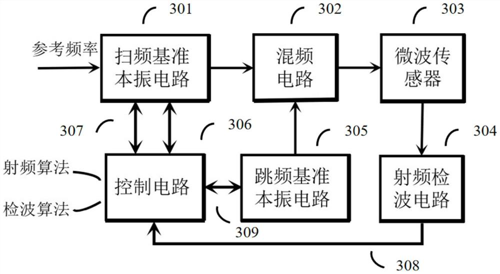
[0034] This embodiment provides a multi-mode microwave detection circuit based on fast frequency hopping technology, such as figure 1 As shown, the circuit includes: frequency sweeping local oscillator circuit (LO1) 301, frequency hopping reference local oscillator circuit (LO2) 305, frequency mixing circuit 302, microwave sensor 303, radio frequency detection circuit 304 and corresponding control circuit 306.

[0035] The control circuit 306 is connected with the frequency sweeping local oscillator reference circuit (LO1) 301 through the control line 307, and connected with the frequency hopping reference local oscillator circuit (LO2) 305 through the control line 309; the radio frequency detection circuit 304 is connected with the control circuit 306 through the data transmission line 308 .

[0036]Among them, the frequency-sweeping local oscillator reference circuit LO1 adopts a wideband fractional frequency-division phase-locked loop (PLL) containing a Sigma-Delta modulati...

Embodiment 2

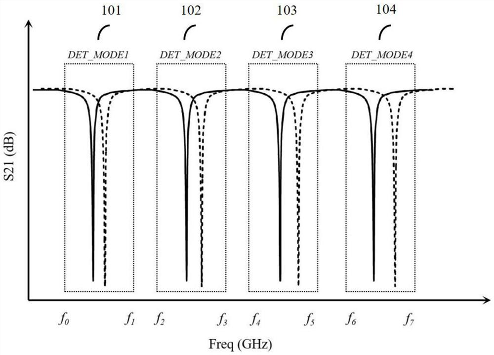
[0041] This embodiment provides a method for multi-mode microwave detection based on fast frequency hopping technology. The microwave detection of a 4-resonant mode is used as an example to introduce the following, see figure 2 , figure 2 Among them, 101, 102, 103 and 104 respectively correspond to the resonant modes in four different operating frequency ranges.

[0042] Among them, 101 corresponds to the DET_MODE1 working frequency range (f0, f1), 102 corresponds to the DET_MODE2 working frequency range (f2, f3), 103 corresponds to the DET_MODE3 working frequency range (f4, f5), 104 corresponds to the DET_MODE4 working frequency range is (f6, f7). In addition, a sufficient frequency interval needs to be reserved between adjacent resonant modes, and this interval is defined as an irrelevant frequency band, which is shown in figure 1 That is (f1, f2), (f3, f4) and (f5, f6).

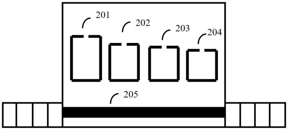
[0043] image 3 for correspondence figure 2 Schematic diagram of the basic structure of the mul...

Embodiment 3

[0090]This embodiment provides an n-mode microwave detection method based on fast frequency hopping technology, which introduces n resonant modes, and each resonant mode can independently respond to changes in the DUT, thereby obtaining n detections within one scan cycle. parameters (ie minimum insertion loss and resonant frequency offset).

[0091] f(DUT)=a 1 f(MODE1)+a 2 f(MODE2)+a 3 f(MODE3)+···+a n f(MODEn)

[0092] Among them, a 1 ,a 2 ,a 3 ...,a n are the fitting coefficients of the corresponding items of the multiple linear regression equation.

[0093] When the DUT changes, the n resonant modes will have different frequency shifts and insertion loss changes in their respective frequency ranges. After the deviation of the resonant frequency of different resonant modes and the change of the insertion loss are obtained by the multi-mode microwave detection system, the change amount of the DUT can be known through the corresponding calculation process.

[0094] A...


PUM


Abstract

The invention discloses a multimode microwave detection system and method based on a fast frequency hopping technology, and belongs to the technical field of microwave sensor detection. The system comprises a frequency sweeping local oscillation reference circuit LO1, a frequency hopping reference local oscillation circuit LO2, a frequency mixing circuit, a microwave sensor with a plurality of resonant membranes, a radio frequency detection circuit and a corresponding control circuit, through the two reference local oscillators and the frequency mixer, rapid frequency sweeping of a working interval of each resonant mode is realized, frequency hopping processing is carried out on irrelevant frequency bands, and the contradiction between real-time performance and aliasing problems in a multimode microwave detection technology is solved; based on the multi-mode microwave detection system, a detection circuit and a detection algorithm are used to realize rapid extraction of single-resonance-mode microwave parameters. Rapid frequency hopping and frequency sweeping of a microwave device in a wide frequency interval are achieved, low stray and phase noise levels are maintained, and the real-time performance and accuracy of microwave detection are guaranteed.

Description

technical field [0001] The invention relates to a multi-mode microwave detection system and method based on fast frequency hopping technology, belonging to the technical field of microwave sensor detection. Background technique [0002] With its high detection accuracy, excellent real-time performance and good reliability, microwave detection technology is widely used in a variety of harsh detection scenarios. The principle of microwave testing is that when the parameters to be measured (Device Under Test, DUT) in the environment change, the microwave parameters such as the resonant frequency, return loss and insertion loss of the microwave device will also change accordingly. Therefore, the degree of change to be measured can be characterized by measuring the frequency shift of the resonance point and the loss of the amplitude of the resonance mode. [0003] Traditional microwave detection devices often have only one resonant mode for detection, and there are fewer microwa...

Claims


Application Information

Patent Timeline
Patent Type & Authority Applications(China)
IPC IPC(8): G01D5/48H03L7/085H03L7/099H03L7/089H03L7/18H03M3/00
CPCY02D30/70
Inventor 梁峻阁付晓冬王琮顾晓峰
Owner JIANGNAN UNIV
Why Eureka
Try Eureka