Radio Frequency Passive Resonant Sensing Feature Demodulation Transformation Circuit

A conversion circuit and sensing technology, applied in electrical components, transmission systems, digital transmission systems, etc., can solve the problems of signal transmission loss and noise, poor driving ability, low demodulation bandwidth, etc., to achieve accurate conversion and testing, frequency The effect of high resolution and low phase noise

Active Publication Date: 2020-02-18
ZHONGBEI UNIV
View PDF2 Cites 0 Cited by
  • Summary
  • Abstract
  • Description
  • Claims
  • Application Information

AI Technical Summary

Problems solved by technology

[0005] Although the above-mentioned instruments have many advantages in function and accessory configuration, they only perform the corresponding basic function verification in the basic technology research process of the laboratory. Such instruments are usually very large in size and weight, and cannot be really suitable for projects. field of practical application
Because it mainly uses radio frequency current-voltage (RF-IV) technology, it is vulnerable to electromagnetic interference, and the stability of the aforementioned large instruments is poor, which leads to essential loss and noise in signal transmission , affecting the test accuracy
The above-mentioned instruments not only have insufficient drive power, but also have low demodulation bandwidth, which greatly reduces test efficiency. At the same time, the drive capability is poor, and the frequency sweep cycle is long, which makes it difficult to meet the current test requirements for device response speed.

Method used


Image

  • Radio Frequency Passive Resonant Sensing Feature Demodulation Transformation Circuit

Examples


Embodiment Construction

[0013] The technical solutions in the embodiments of the present invention are clearly and completely described below in conjunction with the accompanying drawings in the embodiments of the present invention. Obviously, the described embodiments are only part of the embodiments of the present invention, not all of them. Based on the embodiments of the present invention, all other embodiments obtained by those of ordinary skill in the art without creative efforts shall fall within the protection scope of the present invention.

[0014] Many specific details are set forth in the following description to facilitate a full understanding of the present invention, but the present invention can also be implemented in other ways different from those described herein, and those skilled in the art can do so without departing from the connotation of the present invention. Similar promotion, therefore, the present invention is not limited by the specific embodiments disclosed below.

[00...


PUM


Abstract

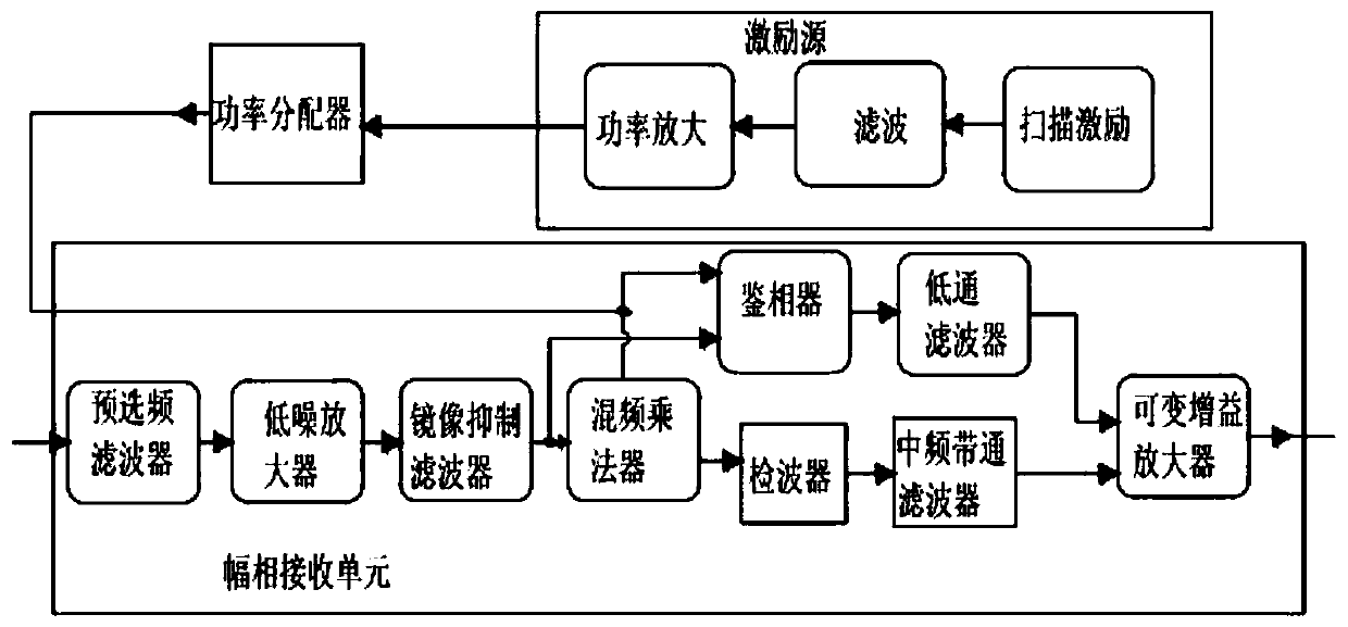
The invention discloses a radio frequency passive resonance sensing characteristic demodulation conversion circuit and relates to the technical field of wireless sensor conversion demodulation testing. The conversion circuit comprises an excitation source, a power distributor and an amplitude-phase receiving unit. The excitation source is divided into a plurality of paths through the power distributor and input to corresponding modules in the amplitude-phase receiving unit. The amplitude-phase receiving unit is used for down-converting a measured signal to an intermediate frequency signal, outputting the signal and sending the signal to a signal conditioning and quantization acquisition module at the back end. Then the signal is converted into discrete time-domain signals for processing atthe back end. The conversion circuit has the advantages of wide output frequency range, high frequency hopping speed, low phase noise, high frequency resolution, high frequency sweeping period, shortresponse time, etc.

Description

technical field [0001] The invention relates to the technical field of wireless sensor conversion and demodulation testing, in particular to a radio frequency passive resonance sensing feature demodulation conversion circuit. Background technique [0002] In the process of network analysis and testing, most research and development units use impedance analysis instruments or vector network analysis instruments produced by Agilent, NI and other companies, British WayneKerr Company, and Japanese HIOKI Company. [0003] AgilentE4991A RF impedance / material analysis provides ultimate impedance measurement performance and powerful built-in analysis functions. It will provide innovative functions for component and circuit designers to measure components within 3GHz to help them in their research and development work. Unlike reflection measurement techniques, the E4991A uses radio frequency current-voltage (RF-IV) technology, which provides more accurate impedance measurements over...

Claims


Application Information

Patent Timeline
Patent Type & Authority Patents(China)
IPC IPC(8): H04B1/00H04B1/713H04L12/26
CPCH04B1/005H04B1/713H04L43/50
Inventor 洪应平熊继军谭秋林黄卡尔梁庭张会新雷程贾平岗
Owner ZHONGBEI UNIV
Why Eureka
Try Eureka