Differential signal output device
a technology of output device and signal, which is applied in the direction of digital transmission, baseband system details, instruments, etc., can solve the problems of deterministic jitter, inability to reduce the jitter caused by the variation of power supply voltage, and adversely affect the receiving side of pulse width, so as to achieve the effect of suppressing jitter in the transmission signal
- Summary
- Abstract
- Description
- Claims
- Application Information
AI Technical Summary
Benefits of technology
Problems solved by technology
Method used
Image

Examples
first embodiment
[0069]A differential signal output device according to a first embodiment of the present invention is shown in FIG. 5.
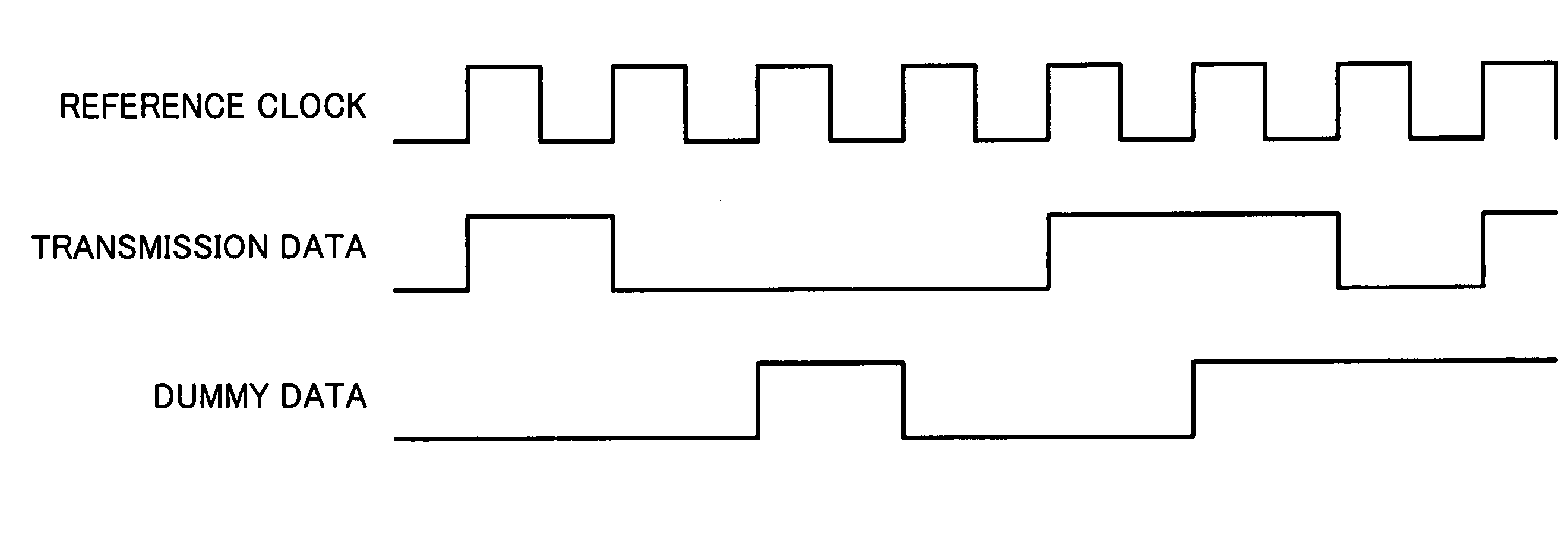
[0070]As shown in FIG. 5, a differential signal output device 1 has a transmission data generation circuit 2 that generates serial transmission data; a dummy data generation circuit 3 that generates serial dummy data that are synchronized with the reference clock of transmission data and change only in bits where the transmission data do not change; a first differential signal generation circuit 4 that amplifies a signal representing the transmission data and generates a differential signal from the amplified signal; and a second differential signal generation circuit 5 that amplifies a signal representing the dummy data and generates a differential signal from the amplified signal.
[0071]The transmission data generation circuit 2 is composed of a logic circuit, etc., of an image processing apparatus, a data link layer, or the like and outputs the serial transmission ...
second embodiment
[0170]A differential signal output device according to a second embodiment of the present invention is shown in FIG. 21. Note that in this embodiment the same constituents as those of the differential signal output device 1 according to the first embodiment of the present invention are denoted by the same reference numerals and the description thereof is omitted.
[0171]As shown in FIG. 21, a differential signal output device 100 has a dummy data generation circuit 13 that generates parallel dummy data from parallel transmission data; a first serializer 14a that is synchronized with a serial clock as the reference clock of the parallel transmission data and serializes the parallel transmission data; a second serializer 14b that is synchronized with the serial clock and serializes the parallel dummy data; a first differential signal generation circuit 4 that amplifies a signal representing the transmission data and generates a differential signal from the amplified signal; and a second...
third embodiment
[0182]A differential signal output device according to a third embodiment of the present invention is shown in FIG. 24. Note that in this embodiment the same constituents as those of the differential signal output device 1 according to the first embodiment of the present invention are denoted by the same reference numerals and the description thereof is omitted.
[0183]As shown in FIG. 24, a differential signal output device 150 has a parallel data generation circuit 17 that generates first parallel data and second parallel data to which every one bit of parallel transmission data is allocated; a first serializer 18a that serializes the first parallel data to be first serial data; a second serializer 18b that serializes the second parallel data to be second serial data; a serial data generation circuit 19a that alternately selects every one bit of the first serial data and the second serial data to generate serial transmission data; an inverter 20 that inverts the second serial data; ...
PUM
 Abstract
Description
Claims
Application Information