
Compact, active alignment fusion splicer with automatic view-angle compensation

a splicer and automatic alignment technology, applied in the field of fiber optics, can solve the problems of affecting the splicing operation in the field, affecting the insertion efficiency of optical fibers, and affecting the insertion efficiency of optical fibers, and achieves the effect of convenient and fast insertion, convenient insertion and alignment, and simple structur

Inactive Publication Date: 2009-02-19
3SAE TECH
View PDF4 Cites 8 Cited by
  • Summary
  • Abstract
  • Description
  • Claims
  • Application Information

AI Technical Summary

Benefits of technology

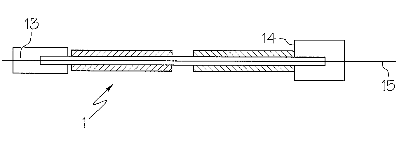
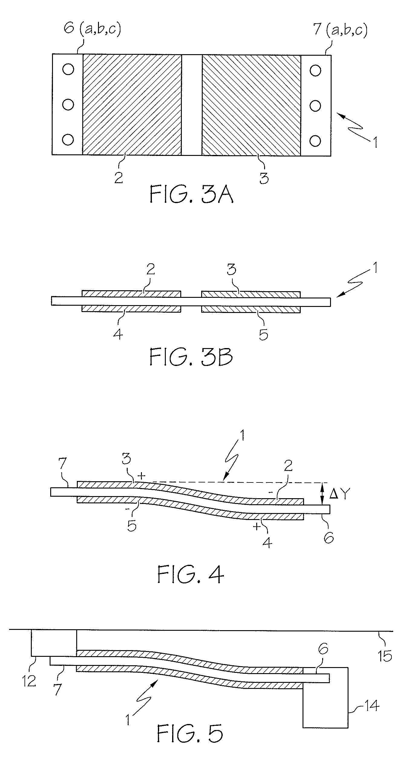
[0016]In accordance with aspects of the present disclosure, provided is an apparatus and a method that enable extremely compact, simple, and cost-effective alignment of optical fibers in an optical fiber fusion splicer. The basis of this alignment method is an “S”-Curve Piezo Bending Actuator. The apparatus comprises a thin strip of elastically flexible material (such as spring steel, beryllium copper, or fiber reinforced polymer) that is coated in four areas with a piezoelectric material (such as barium titanate or other known compounds).

Problems solved by technology

Splicing operations in the field can be hampered by the environment and limited length of slack in the fiber that may be accessible for the technician to manipulate into a splicing device.
Alignment of fibers is a crucial part of the preparation for any splicing operation, but is especially challenging for single mode fibers that have small core diameter.
Mechanical splicing is conceptually simple, and minimal apparatus is required to effect splicing, but a mechanical splice tends to have relatively high and undesirable insertion loss, typically 0.20 dB.
In addition, mechanical splices are generally weaker than the underlying fiber and are vulnerable to degradation of the optical quality of the splice over time, especially under adverse environmental conditions such as varying temperatures and high humidity.
Mechanical splices are generally regarded as being temporary expedients at best and are not useful for high bandwidth systems or permanent joints.
This required precision of alignment presents a substantial technical challenge, especially with single-mode fibers having cores approximately 9 μm diameter.
These purely mechanical approaches do not reliably produce splices that maintain less than 0.10 dB loss.
However, the diffraction limit and the resolution of available electro-optic cameras restrict the precision achievable with PAS, even in systems based on visible light with wavelengths of about 400-700 nm.
The effectiveness of PAS in aligning small diameter, e.g., single mode fibers, is limited.
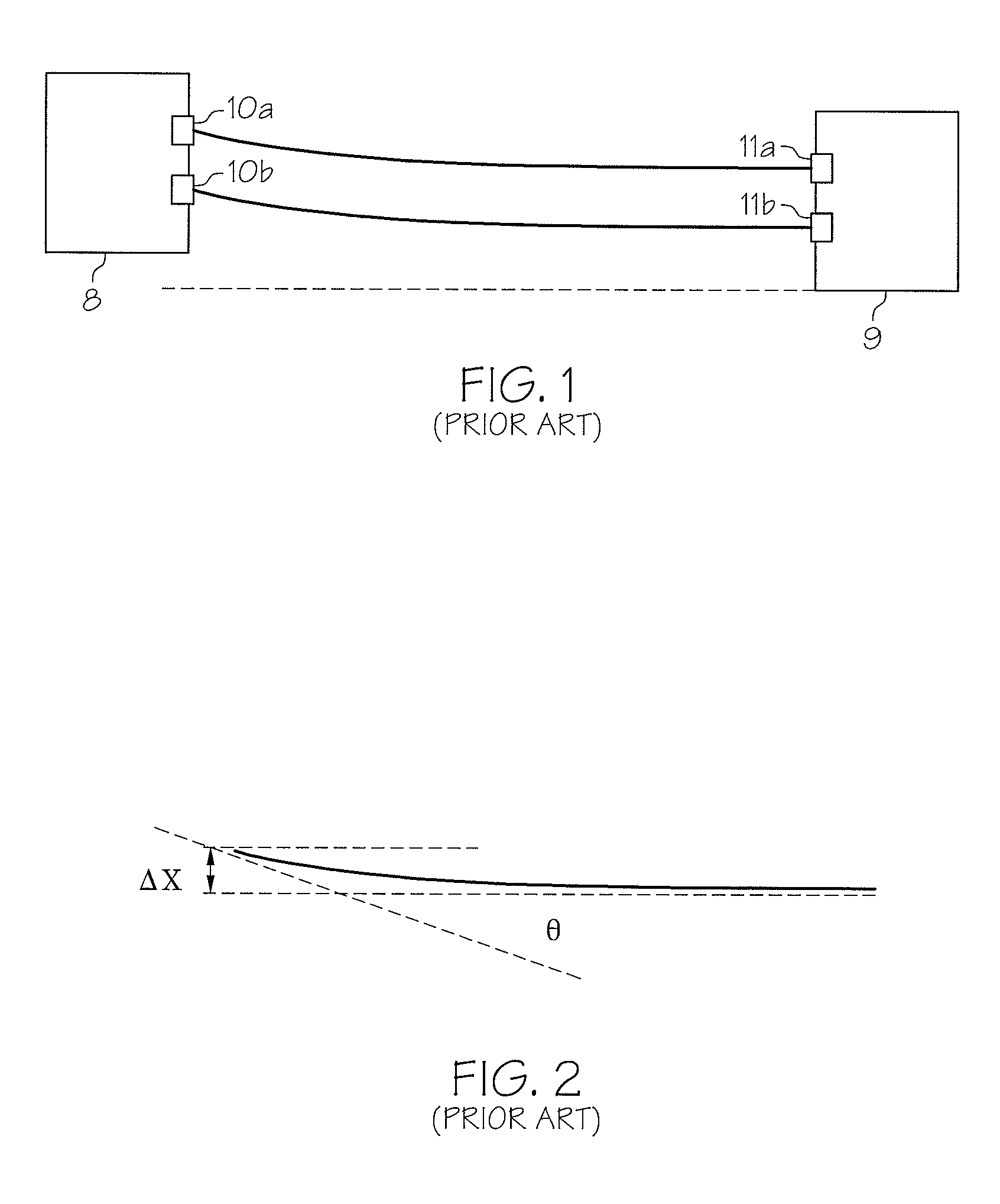
If this angular displacement were conveyed to the optical fiber to be aligned, the angular displacement would produce unacceptable results.
However, the need for connecting blocks, flexible mountings, and paired bimorphs adds to the cost, complexity, and difficulty of alignment using such prior art devices.
To date, the methods and apparatus for carrying out splicing aided either by the PAS, transmission-based alignment, and piezoelectric bimorphs techniques have not been well suited for use outside the laboratory or other similar workplaces.
The required equipment lacks the flexibility, versatility, and ruggedness needed for field use.
Moreover, present equipment is cumbersome and often not operable in the confined spaces frequently encountered during field service.

Method used


Image

  • Compact, active alignment fusion splicer with automatic view-angle compensation
  • Compact, active alignment fusion splicer with automatic view-angle compensation
  • Compact, active alignment fusion splicer with automatic view-angle compensation

Examples


Embodiment Construction

[0042]It will be understood that, although the terms first, second, etc. may be used herein to describe various elements, these elements should not be limited by these terms. These terms are used to distinguish one element from another, but not to imply a required sequence of elements. For example, a first element can be termed a second element, and, similarly, a second element can be termed a first element, without departing from the scope of the present invention. As used herein, the term “and / or” includes any and all combinations of one or more of the associated listed items.

[0043]It will be understood that when an element is referred to as being “on” or “connected” or “coupled” to another element, it can be directly on or connected or coupled to the other element or intervening elements may be present. In contrast, when an element is referred to as being “directly on” or “directly connected” or “directly coupled” to another element, there are no intervening elements present. Oth...


PUM


Abstract

In accordance with various aspects of the present invention, provided is an extremely compact, simple, and cost-effective approach for aligning optical fibers in an optical fiber fusion splicer. The basis of this alignment method is an “S”-Curve Piezo Bending Actuator. The device comprises a thin strip of elastically flexible material (such as spring steel, beryllium copper, or fiber reinforced polymer) that is coated in four areas with a piezoelectric material (such as barium titanate or other known compounds).

Description

CROSS REFERENCES TO RELATED APPLICATIONS[0001]This application claims the benefit of priority under 35 U.S.C. §119(e) from co-pending, commonly owned U.S. provisional patent application Ser. No. 60 / 911,523, entitled COMPACT, ACTIVE ALIGNMENT FUSION SPLICER WITH AUTOMATIC VIEW-ANGLE COMPENSATION, filed Apr. 13, 2007.FIELD OF INTEREST[0002]The present inventive concepts relate to the field fiber optics, and more particularly optical fiber splicers.BACKGROUND[0003]Transmission of data via optical fibers, serving as optical fiber waveguides, is widespread in many applications and industries, such as the telecommunications and computer industries. In many applications, electrical signals are converted into light pulses and propagated through optical fiber. The lights pulses leaving the optical fiber can then be converted back into electrical signals and processed.[0004]Fiber optics has many advantages in many industries. For example, the use of optical fibers can result in significant im...

Claims


Application Information

Patent Timeline
IPC IPC(8): G02B6/255G02B6/00
CPCG02B6/2557G02B6/2551
Inventor WILEY, ROBERT G.CLARK, BRETT G.MEITZLER, JARED
Owner 3SAE TECH
Learn More