Communication system, communication apparatus and communication control method

a communication system and communication control technology, applied in power management, wireless communication, network topologies, etc., can solve the problems of uwb communication scheme, “interference” between wireless communication systems, and inadequacies in setting the reception sensitivity to a level lower, so as to reduce cross-interference with other networks

Inactive Publication Date: 2009-02-19
CANON KK
View PDF18 Cites 3 Cited by
  • Summary
  • Abstract
  • Description
  • Claims
  • Application Information

AI Technical Summary

Benefits of technology

[0020]According to the present invention, it is possible to reduce cross-interference with other networks.

Problems solved by technology

The UWB communication scheme, however, is problematic in that “interference” occurs between wireless communication systems due to the shared use of frequencies.
It is therefore not appropriate to set the reception sensitivity to a level lower than necessary.
However, this method is problematic in that all wireless terminals have to be simultaneously subjected to the interference measurement for adjustment, which requires considerable effort to effect the reception sensitivity adjustment.

Method used


Image

  • Communication system, communication apparatus and communication control method
  • Communication system, communication apparatus and communication control method
  • Communication system, communication apparatus and communication control method

Examples


embodiment 1

[0039]

[0040]A configuration of a wireless frame that is defined by the MAC protocol of the UWB communication scheme will be described first.

[0041](1) Overall Configuration of Wireless Superframe

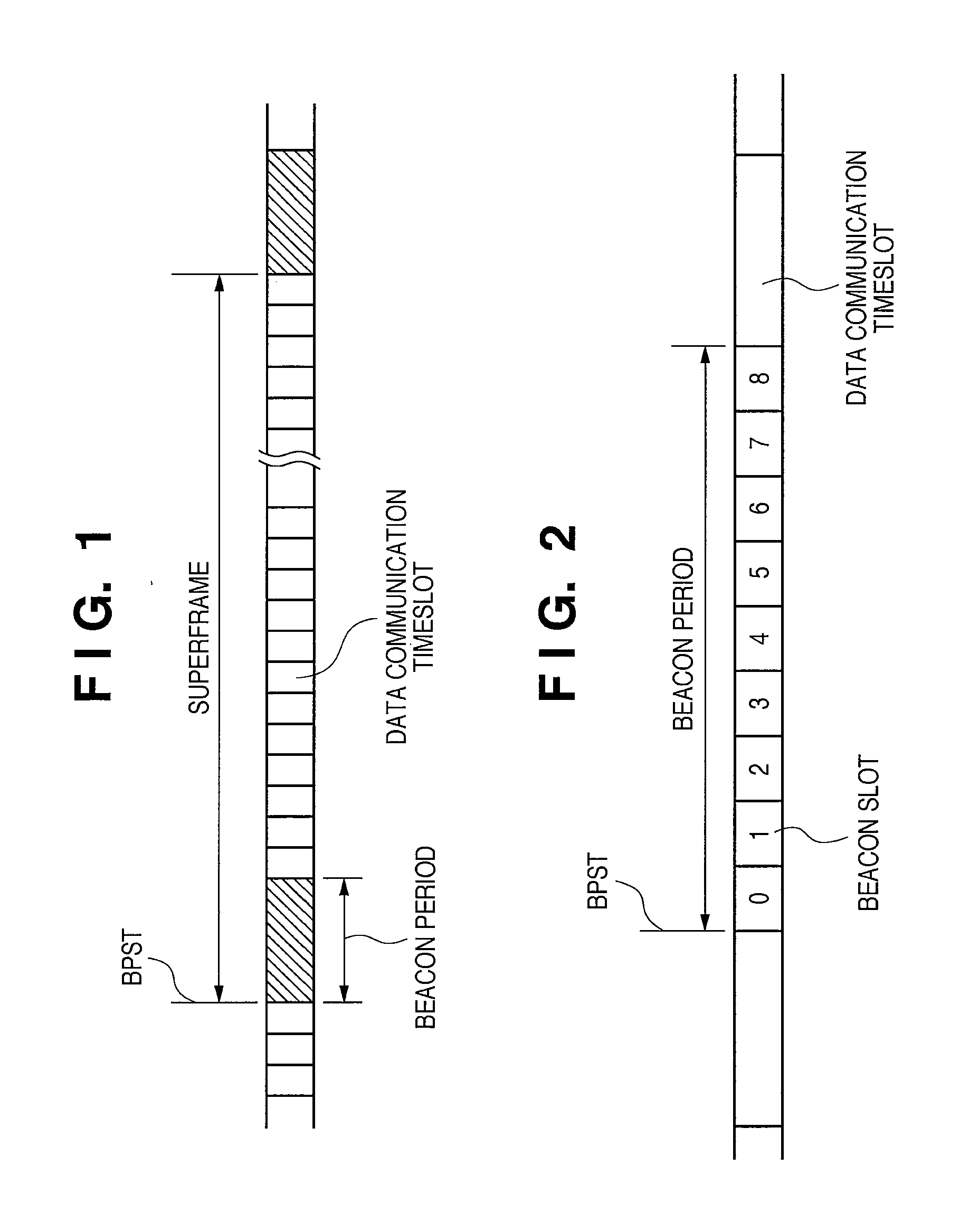
[0042]FIG. 1 is a diagram illustrating the overall configuration of a wireless superframe that is defined by the MAC protocol. According to the MAC protocol, access timing between wireless terminals is controlled based on a superframe having a fixed time length that is repeatedly generated.

[0043]The time length of a superframe is about 65 milliseconds, and this superframe is divided equally into 256 timeslots. Which of these timeslots can be used as data communication timeslots is determined through transmission / reception of control signals called “beacons” between wireless terminals.

[0044]At least one timeslot located in the beginning of a superframe is an allocated region that the wireless terminal uses to transmit the beacon, and this region is called a “beacon period”.

[0045](2) Configurat...

embodiment 2

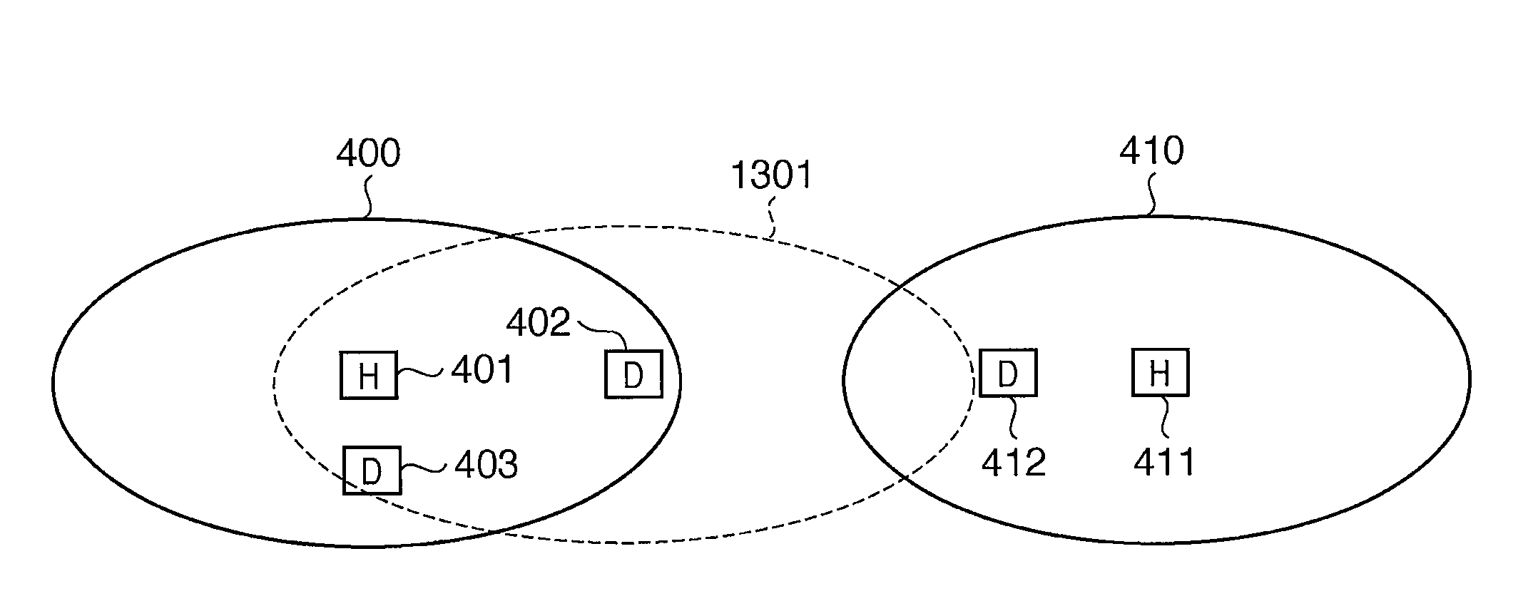
[0141]Embodiment 1 described above has discussed a configuration in which the control of the reception sensitivity of the Wireless USB device 402 is executed by gradually lowering the reception sensitivity, but the present invention is not intended to be limited thereto, and the reception sensitivity may be controlled by gradually increasing the reception sensitivity. In this case, the Wireless USB host 401 causes the Wireless USB device 402 to lower its reception sensitivity to a predetermined value before proceeding to step S1201 of FIG. 12. After that, the process ranging from steps S1201 to S1203 is performed. In step S1204, it is determined whether or not there is a wireless terminal that is operated in asynchronization with the Wireless USB host 401. If no wireless terminal that is operated in asynchronization is found, the Wireless USB host 401 transmits an instruction to raise the reception sensitivity by one level to the Wireless USB device 402. Then, the above process is r...


PUM


Abstract

To adjust reception sensitivity suitable for avoiding cross-interference with another wireless communication system with an easy method. In order to achieve the above object, a control station that controls wireless communication of a dependent station determines whether or not a beacon received by the dependent station includes a beacon transmitted by a wireless terminal that is operated in asynchronization with the control station, and continues to transmit an instruction to lower the reception sensitivity of the dependent station to the dependent station until the beacon received by the dependent station does not include a beacon transmitted by the asynchronous wireless terminal.

Description

BACKGROUND OF THE INVENTION[0001]1. Field of the Invention[0002]The present invention relates to a technique for controlling communication within a network.[0003]2. Description of the Related Art[0004]A scheme that wirelessly connects devices located in close proximity (about 10 meters) to one another is called a “WPAN”, and is defined separately from WLAN.[0005]Currently, as a standard for WPAN that uses a UWB (Ultra Wide-Band) communication scheme, ECMA International, which is a standards development organization, has published ECMA-368 which provides PHY and MAC layer specifications. Wireless USB and like standards are defined as protocols which operate at communication layers above this ECMA-368 standard.[0006]In the UWB communication scheme, the timing at which each wireless terminal accesses another wireless terminal is controlled to prevent a “collision” between wireless frames that occurs when a plurality of wireless terminals transmit wireless frames simultaneously. Media A...

Claims


Application Information

Patent Timeline
Patent Type & Authority Applications(United States)
IPC IPC(8): H04B15/00H04B7/005H04W24/00H04W24/10H04W28/00H04W52/52H04W74/04H04W84/12
CPCH04W16/14H04B1/109
Inventor KANDA, TETSUOEGUCHI, TADASHI
Owner CANON KK
Why Eureka
Try Eureka