System and method for augmentation of endoscopic surgery

a technology of endoscopic surgery and system, applied in the field of endoscopic surgery, can solve the problems of unsatisfactory convenience of surgeons, unresolved problems, and system does not address the problem of providing surgeons with convenient means, so as to facilitate the use of invention

Inactive Publication Date: 2009-02-19
IBM CORP
View PDF47 Cites 114 Cited by
  • Summary
  • Abstract
  • Description
  • Claims
  • Application Information

AI Technical Summary

Benefits of technology

[0014]An objective of this invention is to provide an improved method to obtain and display accurate information about the position of an anatomical feature within a patient's body.
[0015]Also an objective of this invention is to provide an improved method of positioning endoscopic cameras and other surgical instruments within a patient's body.
[0016]A further objective of this invention is to provide an interface for a surgeon to accurately position an endoscopic camera and / or other surgical instruments within a patient's body without removing his hands from the instrument.

Problems solved by technology

This class of systems has two salient characteristics in common: First, the surgeon using the system cannot directly manipulate the patient's anatomy with his fingers, and second, the surgeon cannot directly observe what he is doing.
However, in order for these advantages to be realized, a number of problems need to be solved.
However, this system does not address the problem of providing the surgeon with a convenient means of controlling the view available through an endoscopic device or of providing the surgeon with means of interactively manipulating surgical instruments in response to intraoperative imaging and other sensory information.
Difficulties of this approach include: (a) the surgeon (or an assistant) must still determine which direction to deflect the endoscope tip to provide a desired view and, consequently, must keep track of the relationship between the endoscope tip and the anatomical structures being observed; (b) these corrections must be made continually, distracting the surgeon from more important matters; and (c) the use of voice commands for this purpose is subject to errors, potentially distracting to the surgeon, and may make the use of voice for communication between the surgeon and operating room personnel more difficult.
These devices do not, however, simplify the surgeon's problem of controlling the endoscopic camera to obtain a desired view, either by himself or by communicating with a skilled operator.

Method used


Image

  • System and method for augmentation of endoscopic surgery
  • System and method for augmentation of endoscopic surgery
  • System and method for augmentation of endoscopic surgery

Examples


Embodiment Construction

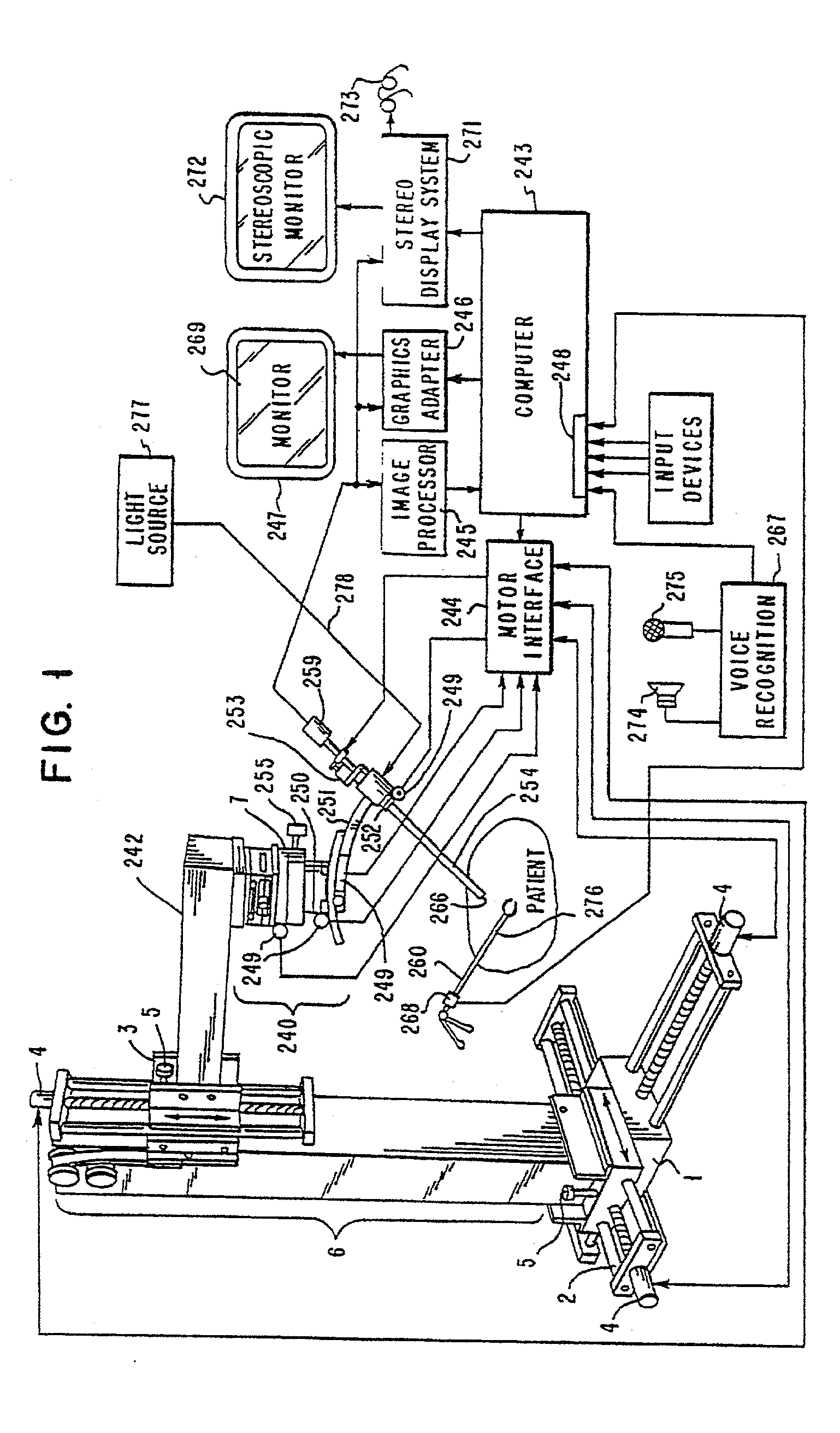
[0031]Referring to FIG. 1, there is shown a schematic view of a system for use in computer augmentation of laparoscopic or similar procedures. The system generally comprises a manipulator apparatus or robot 242, a computer 243, a drive motor interface 244, a monoscopic monitor 247 with a suitable image processor 245 and graphics adaptor 246, a stereoscopic monitor 272 with suitable stereo display system 271, and a terminal 248 for connecting additional input devices to computer 243.

[0032]A manipulator similar to the manipulator 242, used in this preferred embodiment, is described in detail in U.S. application Ser. No. 07 / 714,816 filed on Jun. 13, 1991.

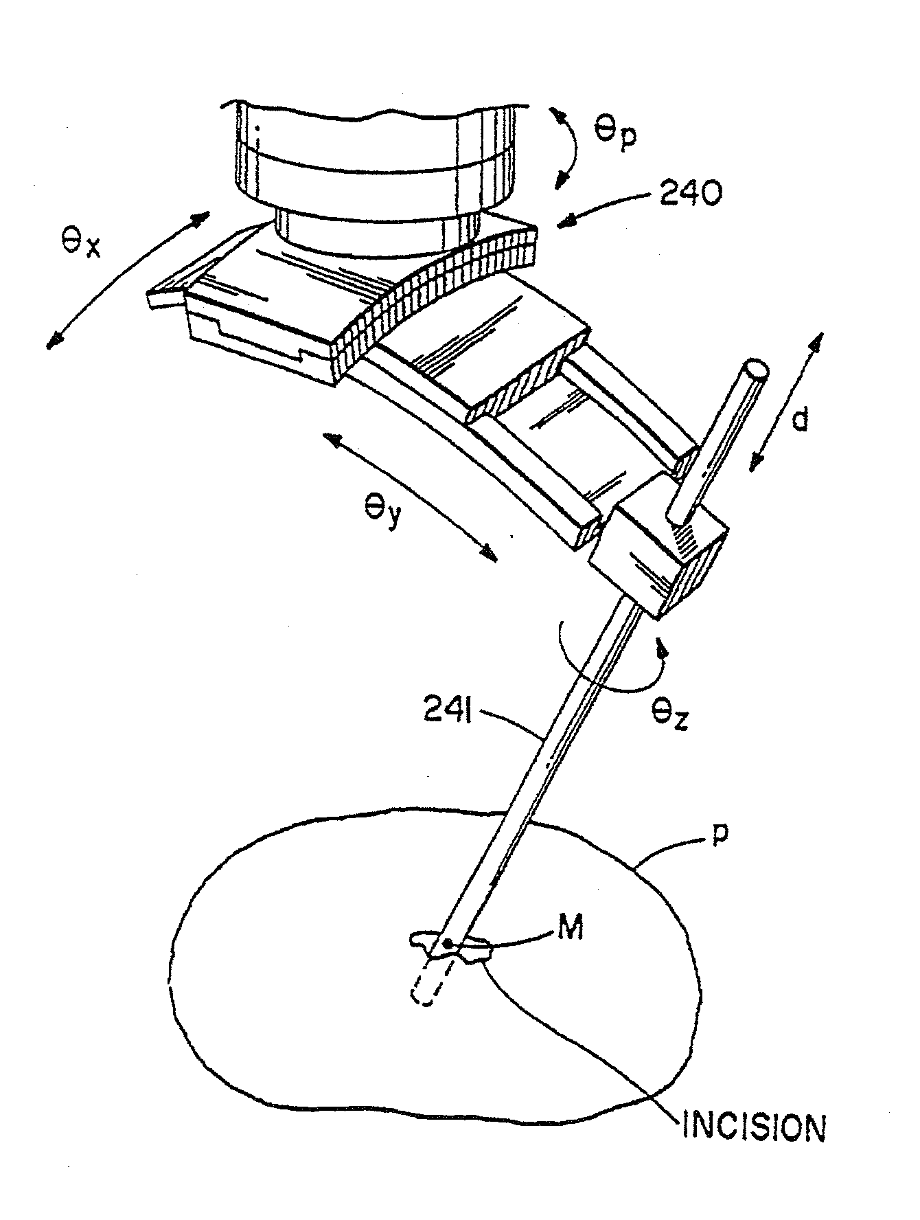
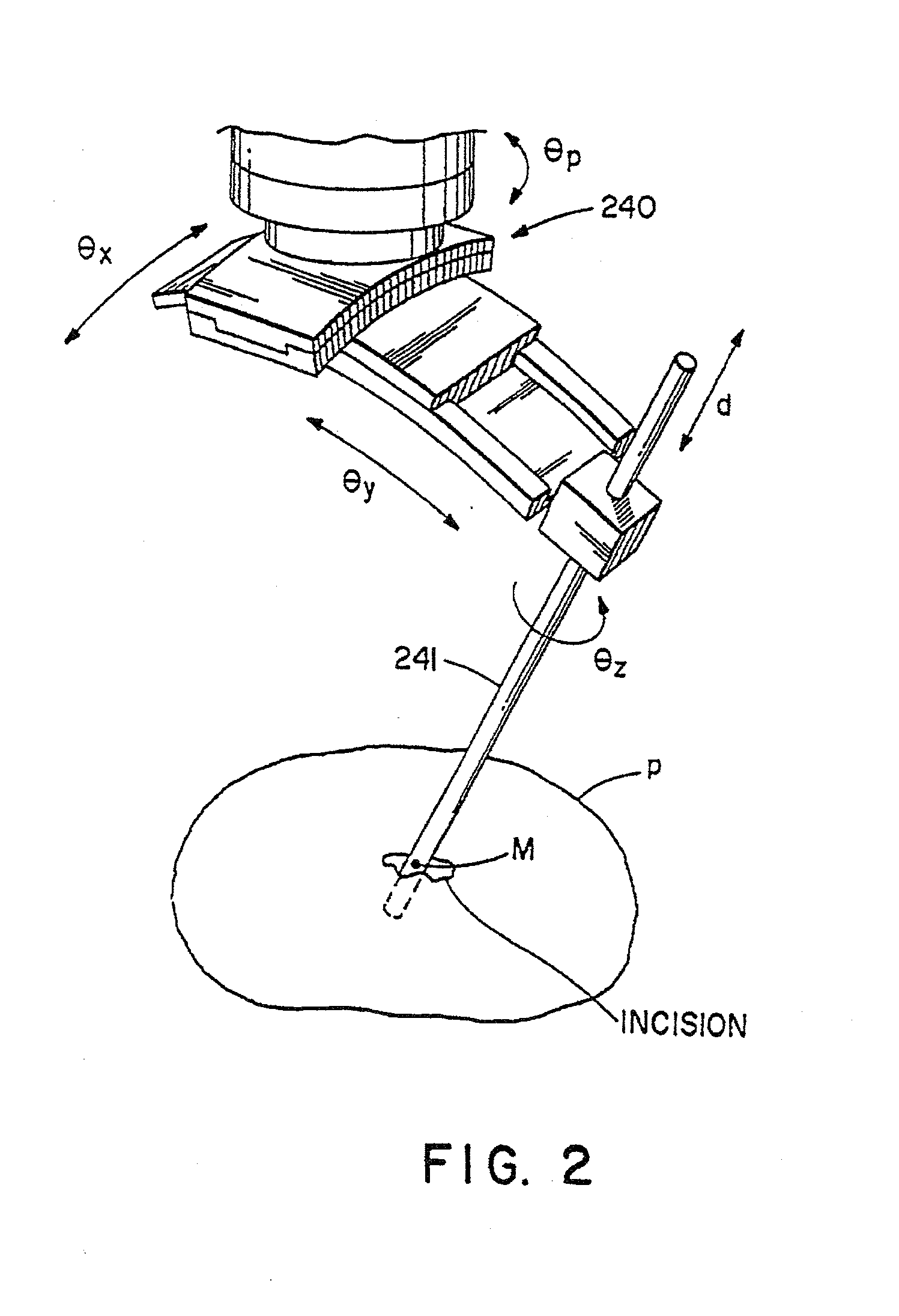
[0033]Referring to FIGS. 1 and 2, the manipulator 242 comprises a proximal rectilinear manipulator 6 and a remote center-of-motion distal manipulator 240. The proximal manipulator 6 comprises three mutually orthogonal sliding motion sections 1, 2, and 3, which provide motion in the X, Y, and Z directions. Sections 1, 2, and 3 are equip...


PUM


Abstract

A robotic device for use in surgery includes a first surgical instrument having a proximal end, a distal end, and a shaft extending therebetween, the distal end of the first instrument and adjacent shaft being insertable distally into a first incision; a first manipulator movably supporting the first instrument; a plurality of motorized drives coupled to the manipulator; an input device having an input movable in two degrees of freedom; and a computer coupling the input device to the motorized drives so that the motorized drives effect a motion of the first surgical instrument in response to movement of the input, a center of the motion located along the shaft at the incision when the first instrument is used during surgery.

Description

CROSS-REFERENCE TO RELATED APPLICATION(S)[0001]The present application is a division of U.S. patent application Ser. No. 09 / 595,186, filed on Jun. 16, 2000, which is a continuation of U.S. patent application Ser. No. 09 / 325,761, filed on Jan. 26, 1995, which is a division of U.S. patent application Ser. No. 07 / 889,215, filed on May 27, 1992, the disclosures of which are incorporated by reference herein.FIELD OF THE INVENTION[0002]This invention relates to the field of endoscopic surgery. More specifically the invention relates to obtaining accurate positional information about an anatomical structure within a patient's body and using this information to accurately position endoscopic cameras and surgical instruments within the patient's body.BACKGROUND OF THE INVENTION[0003]Systems have been developed to augment a human surgeon's ability to perform surgery on a patient by providing the surgeon with intraoperative images of anatomical structures within the patient's body. Typically, ...

Claims


Application Information

Patent Timeline
Patent Type & Authority Applications(United States)
IPC IPC(8): A61B19/00A61B1/00A61B1/04A61B1/05A61B17/00B25J9/04B25J17/02
CPCA61B1/00193A61B1/00009A61B17/00234A61B19/20A61B19/201A61B19/22A61B19/50A61B19/52A61B19/5212A61B19/5244A61B2017/00022A61B2017/00203A61B2019/2276A61B2019/2292A61B2019/4868A61B2019/502A61B2019/507A61B2019/5255A61B2019/5265A61B2019/5268A61B2019/5291A61B2019/5437A61B2019/5445B25J9/04B25J17/0275G05B2219/37074G05B2219/40418G05B2219/40609G05B2219/45123G05B2219/45166A61B1/05A61B90/10A61B2034/742A61B2034/102A61B90/36A61B2034/2055A61B2034/2068A61B2090/3945A61B34/20A61B34/70A61B90/361A61B90/11A61B34/76A61B2090/0813A61B34/10A61B2034/107A61B2034/2065A61B2090/365A61B2090/3937A61B1/000094A61B1/00194
Inventor FUNDA, JANEZLAROSE, DAVID ARTHURTAYLOR, RUSSELL HIGHSMITH
Owner IBM CORP
Why Eureka
Try Eureka