Bone support devices and methods

Inactive Publication Date: 2009-02-19
JUVENTAS
View PDF7 Cites 29 Cited by
  • Summary
  • Abstract
  • Description
  • Claims
  • Application Information

AI Technical Summary

Benefits of technology

[0050]Provided herein is a method for reducing the risk of fracturing a bone of a patient comprising implanting a multiple-rod scaffold within a bone. Provided herein is a method for reducing the risk of fracturing a bone of a patient comprising implanting a device comprising a multiple-rod scaffold within a bone. Multiple-rod scaffolds and devices comprising a multiple-rod scaffold as described herein may be used in the methods provided herein. The implanting may comprise orienting each rod substantially parallel to each other rod, and positioning each rod at a displaced position in the bone relative to each other rod.
[0051]Provided herein is a method for reducing the risk of fracturing a bone of a patient comprising implanting a device in a bone at a first orientation and a first position relative to the bone, wherein the device comprises an implant and the implant comprises a deployable element adapted to deploy within the bone at a second orientation and second position relative to the bone. Provided herein is a method for reducing the risk of fracturing a bone of a patient comprising implanting an implant in a bone at a first orientation and a first position relative to the bone, wherein the implant comprises a deployable element adapted to deploy within the bone at a second orientation and second position relative to the bone. Devices comprising implants having deployable elements and implants having deployable elements as described herein may be used in embodiments of the method. The method may further comprise deploying the deployable element at the second orientation and second position relative to the bone.
[0052]Provided herein is a method for reducing the risk of fracturing a bone of a patient comprising implanting a means for absorbing force on a bone. Provided herein is a method for reducing the risk of fracturing a bone of a patient comprising implanting a device comprising a means for absorbing force on a bone. In some embodiments of the methods, the force results from a fall. In some embodiments of the methods, the force results from normal use. Normal use may include, for non-limiting example, at least one of walking, lifting, bending, sitting, running, leaning, and standing. In some embodiments, the force results from normal loading of the bone. Normal loading may include loads resulting from, for non-limiting example, at least one of walking, lifting, bending, sitting, running, leaning, and standing. Devices comprising means for absorbing force on a bone as described herein, and means for absorbing force on a bone as described herein may be used with embodiments of the method. The method may further comprise securing the means for absorbing force within tissue. Means for securing the means for absorbing force as described herein may be used in embodiments of the method. Devices comprising means for securing the means for absorbing force as described herein may be used in embodiments of the method.
[0053]Provided herein is a method for reducing the risk of fracturing a bone of a patient comprising implanting a means for deflecting force on a bone. Provided herein is a method for reducing the risk of fracturing a bone of a patient comprising implanting a d

Problems solved by technology

Osteoporosis is characterized by low bone mass and structural deterioration of bone tissue, leading to bone fragility and an increased susceptibility to bone fractures, especially of the hip bones, spine, and wrist bones.
Osteoporosis occurs primarily as a result of normal aging, but can arise as a result of impaired development of peak bone mass or excessive bone loss during adulthood.
Hip fractures often result in hospitalization, and complete recovery is difficult—if it is ever achieved.
Many patients require long term nursing home care, and many are permanently disabled following a hip fracture.
Too

Method used


Image

  • Bone support devices and methods
  • Bone support devices and methods
  • Bone support devices and methods

Examples


Embodiment Construction

[0094]While preferred embodiments of the present invention have been shown and described herein, it will be obvious to those skilled in the art that such embodiments are provided by way of example only. Numerous variations, changes, and substitutions will now occur to those skilled in the art without departing from the invention. It should be understood that various alternatives to the embodiments of the invention described herein may be employed in practicing the invention. It is intended that the following claims define the scope of the invention and that methods and structures within the scope of these claims and their equivalents be covered thereby.

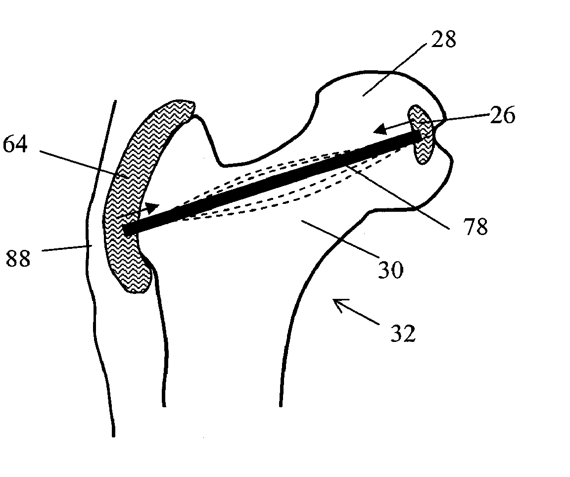
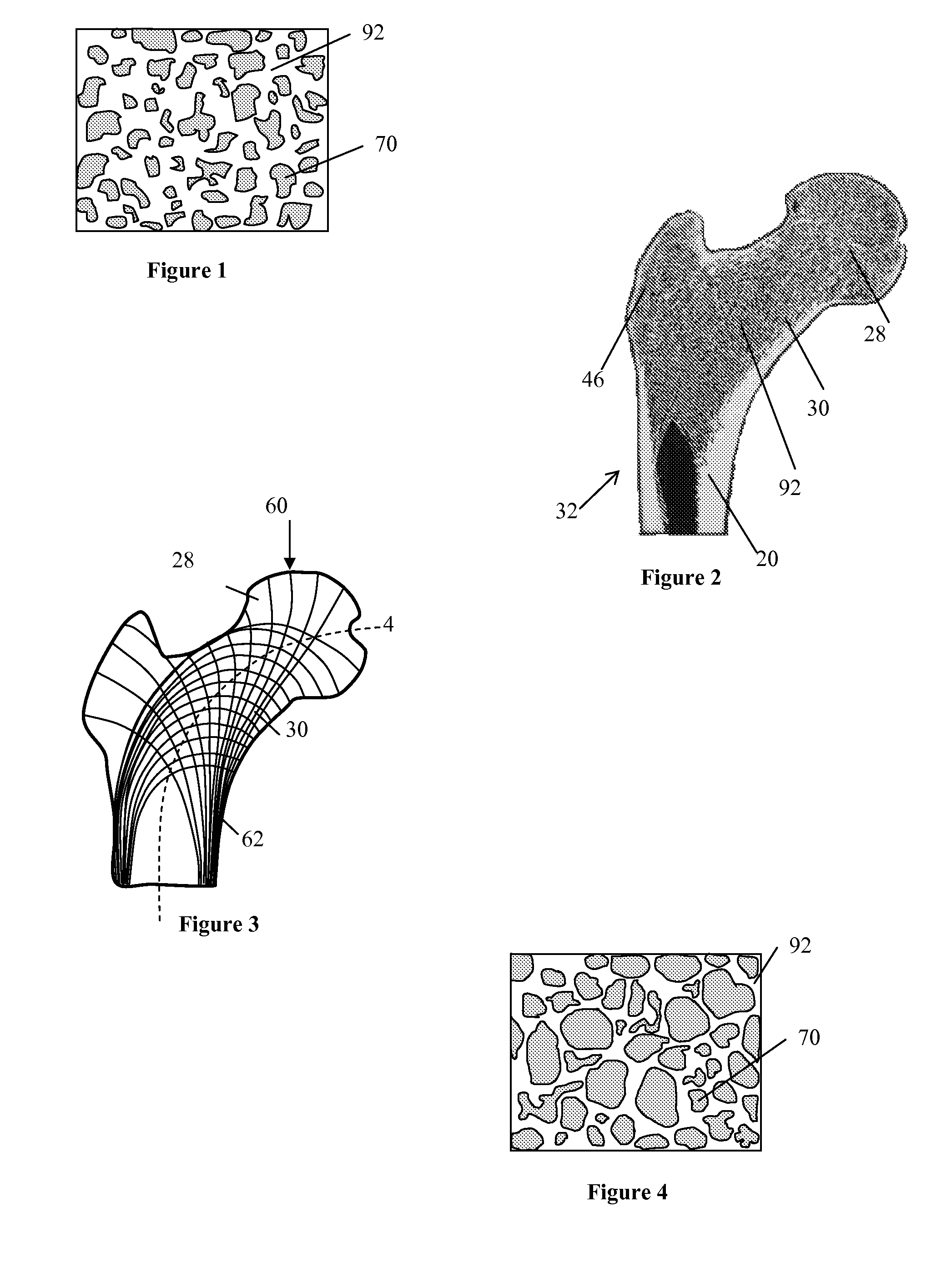
[0095]Normal bone consists of spongy bone, which can be described as open networks of branching trabecular bone which allows bone to withstand stresses in different directions. FIG. 1 shows a depiction of young trabecular bone 92 and pores 70. FIG. 2 shows a cross-section of normal femur bone 32, including the femur head 28, femoral n...


PUM


Abstract

Provided herein are methods, devices and kits for reducing the risk of fracturing a bone. A device is provided comprising an implantable pad for absorbing, deflecting, and/or diffusing an exterior impact force on a bone. A device is provided for strengthening and/or reinforcing a bone at typical fracture sites prior to fracture and/or along lines of tension and compression forces. The devices may comprise a coil adapted to be implanted in the bone. The device may comprise a rod adapted to be implanted in the bone. The devices may comprise a deployable element adapted to be deployed in the bone. The device may comprise a scaffold adapted to be implanted in the bone. The device may comprise a reinforcing material and/or means for reinforcing and/or strengthening the bone at typical fracture sites prior to fracture and/or along lines of tension and compression forces.

Description

CROSS-REFERENCE[0001]This application claims the benefit of U.S. Provisional Application No. 60 / 945,007, filed Jun. 19, 2007, which application is incorporated in its entirety herein by reference.BACKGROUND OF THE INVENTION[0002]Osteoporosis is characterized by low bone mass and structural deterioration of bone tissue, leading to bone fragility and an increased susceptibility to bone fractures, especially of the hip bones, spine, and wrist bones. Osteoporosis occurs primarily as a result of normal aging, but can arise as a result of impaired development of peak bone mass or excessive bone loss during adulthood. The National Osteoporosis Foundation estimated that one in four men and one in two women and over the age of 50 will have an osteoporosis-related fracture in his / her remaining lifetime. The number of fractures is expected to grow as the aging population grows. The World Health Organization (WHO) estimated in 2003 that the number of osteoporosis fractures would double over the...

Claims


Application Information

Patent Timeline
IPC IPC(8): A61F2/02A61F2/08A61B17/56
CPCA61B17/742
Inventor ESSENMACHER, KIRK
Owner JUVENTAS
Why Eureka
Try Eureka