Reduced-Noise Electric Brake Actuator

a technology of electric brake actuator and reduced noise, which is applied in the field of brakes, can solve the problems of affecting the precision of the torque transmission of the entire gear assembly, and the failure to achieve the expected noise damping of the entire brake actuator,

Active Publication Date: 2009-02-26
LUCAS AUTOMOTIVE GMBH
View PDF6 Cites 32 Cited by
  • Summary
  • Abstract
  • Description
  • Claims
  • Application Information

AI Technical Summary

Benefits of technology

[0008]According to a first aspect of the invention, an electrically driven brake actuator is provided which comprises an electric motor for producing a torque, a device for torque transmission and an element for torque delivery, wherein the electric motor has a motor shaft and the device for torque transmission has a gear mechanism with a gear shaft which is parallel to the motor shaft, wherein the torque is transmitted from the electric motor to the gear mechanism by means of a belt drive and the distance between the motor shaft and the gear shaft is fixed by means of a rigid spacer. Here opposite ends of the spacer are located on different sides of the plane which is defined by a belt of the belt drive. In other words, the spacer extends, for example, in the shape of an S or a Z through the belt plane in order thereby to achieve improved fixing.
[0011]The belt gear mechanism and in particular the belt can guarantee isolation of the electric motor, in terms of vibrations, from the subsequent actuator components and therefore vibration damping. The belt can be made of a resilient material in order to assist the vibration damping.
[0012]According to a first variant, the belt can be a toothless belt. According to a second variant, the belt is formed as a toothed belt. In the case of the second variant the toothed belt and the pulleys can have a pitch, corresponding to one another, of less than 2.5 mm and in particular of less than 1.5 mm. The impact on entry is reduced and the tendency to vibrations decreases as the pitch decreases. The toothed belt and the pulleys can be helically toothed, whereby the tendency to vibrations decreases further and a more uniform torque transmission between the belt and the pulley is obtained.
[0015]As compared with the hub and / or with the ring gear, the vibration-damping element expediently consists of a softer material, preferably an at least slightly resilient material with high inherent damping. The vibration-damping element is preferably of a constant thickness, related to the extent of the pulley shaft; however a non-uniform thickness may also be a possibility in some cases. The vibration-damping element is usually formed so that it is at a constant average distance from the axis of rotation. The element can be formed along a circular line or any desired curve. In order to influence the torque transmission and vibration damping characteristic of the pulley, the radial extent of the vibration-damping element can vary. Uniform curved projections, for example, have proved successful in practice.
[0024]The electric motor can have a number of poles of more than 5 to assist low-vibration operation. The number of poles can also be 7 in particular. The electric motor can also have a finely balanced armature. A glued flux sheet and / or damped brushes are also possible. A further reduction of noise can be achieved by using a brushless electric motor and / or a reduced-torque electric motor. Furthermore, the electric motor can be operated in a speed range which leads to reduced operating noise, for example by means of an electronic control system.

Problems solved by technology

It has become apparent that, in spite of the good noise-damping properties of belt gear mechanisms, the expected noise damping of the entire brake actuator is often not achieved, as in some cases other components of the actuator transmit the vibrations produced by the electric motor around the belt unit.
Solutions which permit complete isolation of the structure-borne noise caused by the electric motor from a subsequent drive train are expensive to manufacture and assemble, are often susceptible to faults on account of the high number of parts used and, moreover, may impair the precision in the torque transmission of the entire gear assembly.

Method used


Image

  • Reduced-Noise Electric Brake Actuator
  • Reduced-Noise Electric Brake Actuator
  • Reduced-Noise Electric Brake Actuator

Examples


Embodiment Construction

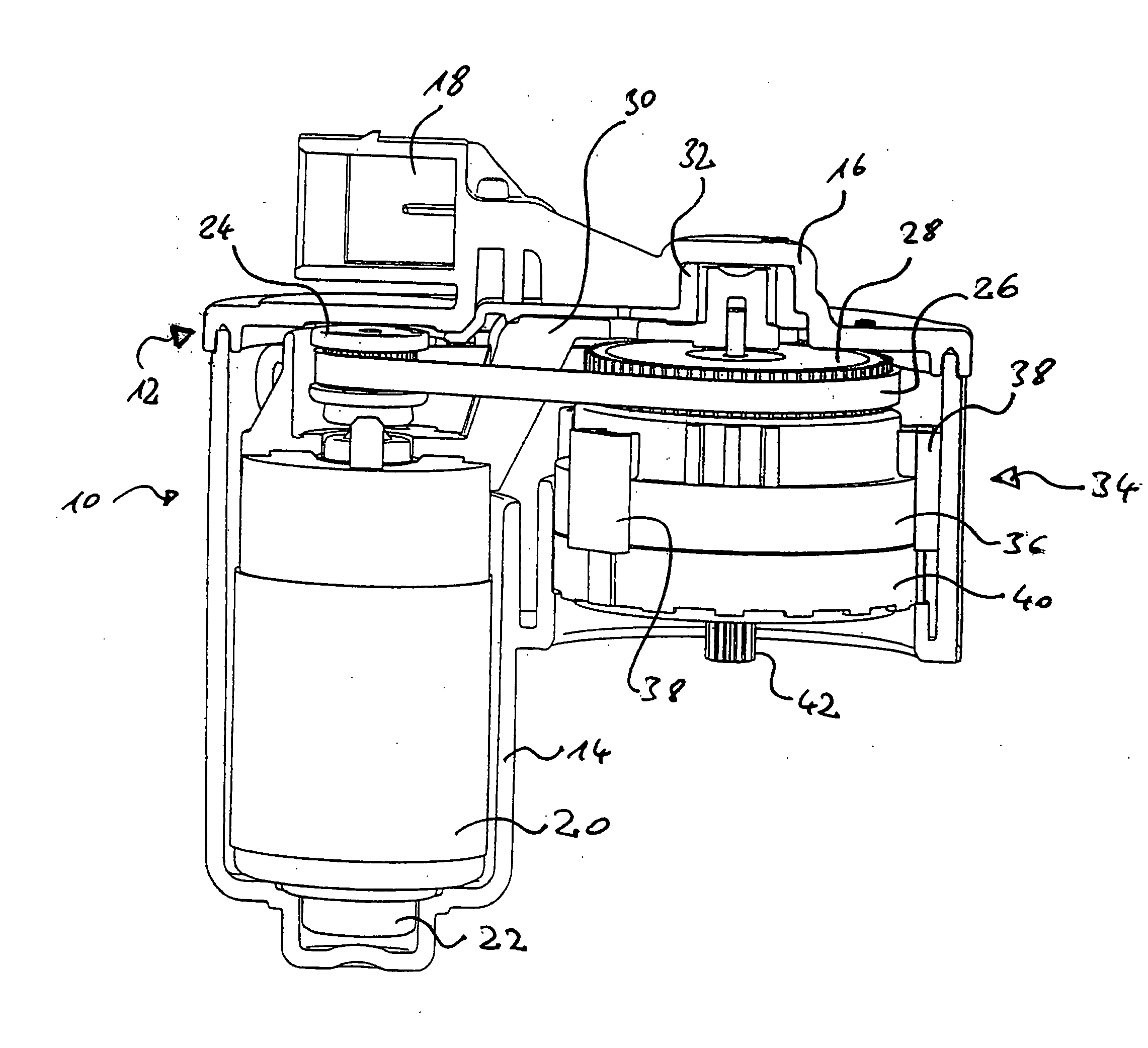
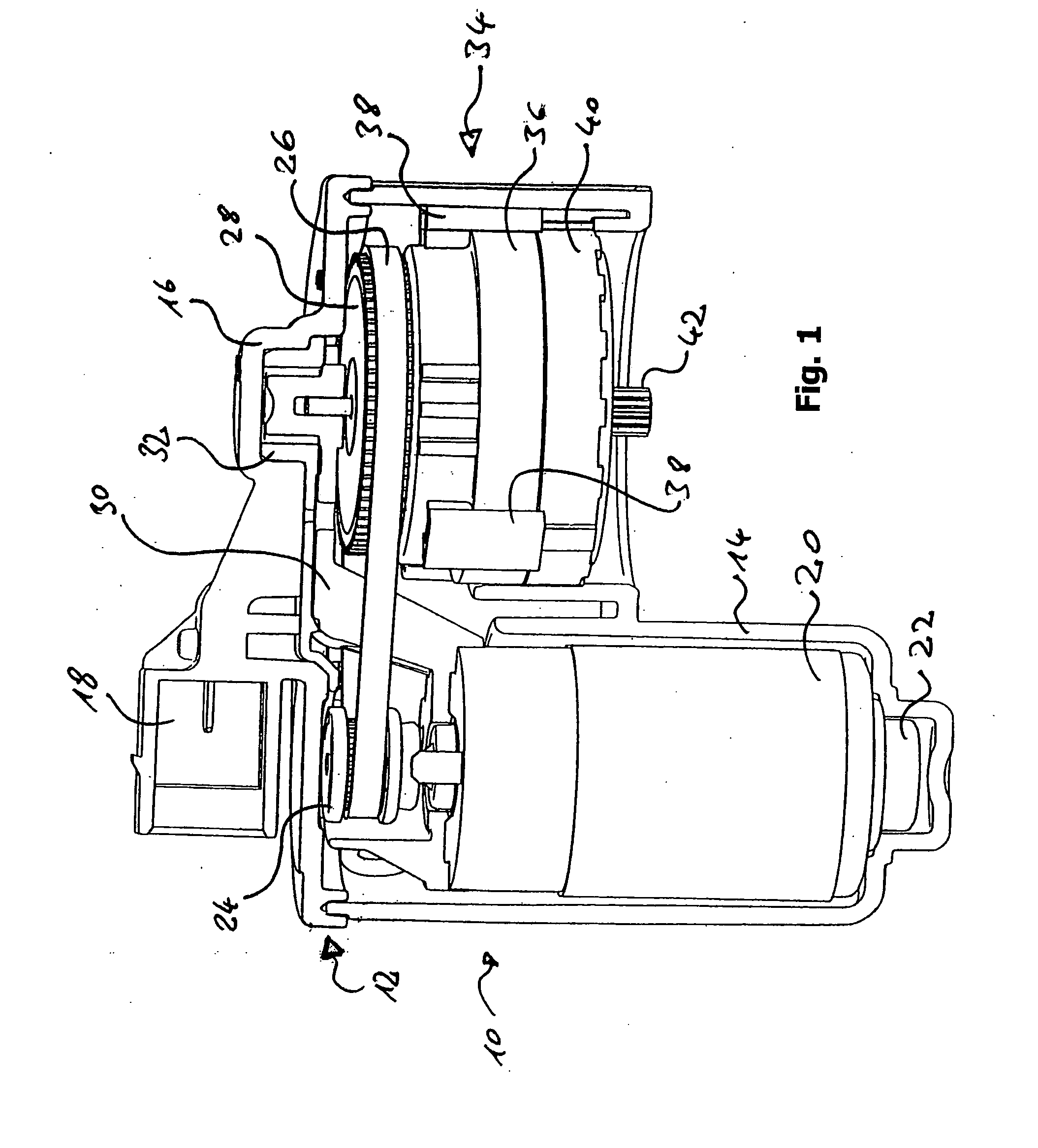
[0033]An embodiment of a brake actuator which can be actuated by an electric motor is described in the following. The described brake actuator delivers a torque which can be used to actuate a vehicle brake (not represented).

[0034]FIG. 1 shows a partial section through a brake actuator 10 with an actuator housing 12 consisting of a housing body 14 and a housing cover 16. The housing cover 16 includes a connection socket 18 and is seated on the edge of the housing body which is at the top in FIG. 1. The connection socket 18 is electrically connected to the connections of an electric motor 20.

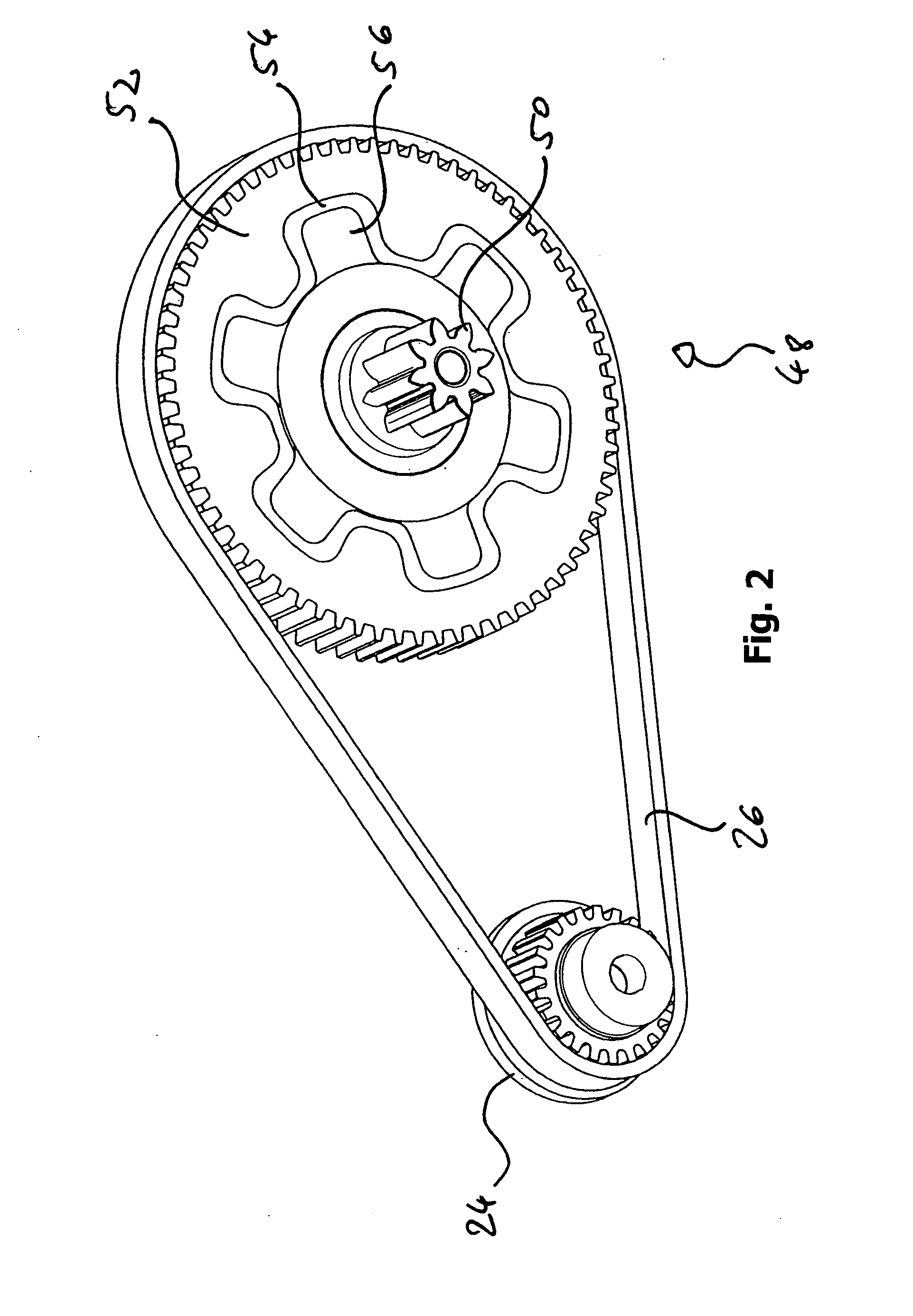
[0035]The electric motor 20 is held with a precise fit in a recess of the housing body 14 and is supported at its bottom end at the bottom of the housing body 14 by means of an element 22 of vibration-damping material. The electric motor 20 bears a first toothed belt pulley 24 on its side which faces the housing cover. This first toothed belt pulley is connected to a shaft of the electric motor 20...


PUM


Abstract

An electric brake actuator is described. The actuator comprises a housing, an electric motor, a device for torque transmission and an element for torque delivery. The device for torque transmission is a gear mechanism with a gear shaft which is parallel to the motor shaft, wherein the torque is transmitted from the electric motor to the gear mechanism by means of a belt drive. The distance between the motor shaft and the gear shaft is fixed by means of a rigid spacer, the opposite ends of which are located on different sides of the plane which is defined by a belt of the belt drive.

Description

CROSS-REFERENCE TO RELATED APPLICATIONS[0001]This application is a National Stage of International Application No. PCT / EP2007 / 001372 filed Feb. 16, 2007, the disclosures of which are incorporated herein by reference in entirety, and which claimed priority to German Patent Application No. 10 2006 007 755.5 filed Feb. 20, 2006, the disclosures of which are incorporated herein by reference in entirety.BACKGROUND OF THE INVENTION[0002]The invention relates to the field of brakes and in particular of motor vehicle brakes. To be more precise, the invention relates to a brake actuator which can be actuated by an electric motor.[0003]Brake actuators which can be actuated by an electric motor are used both for service brakes and for hand brakes (also called parking brakes) of motor vehicles. The advantage of this design with respect to brakes which are actuated solely by means of cables or hydraulics is the fact that the driver does not have to apply a high muscular force in order to actuate...

Claims


Application Information

Patent Timeline
Patent Type & Authority Applications(United States)
IPC IPC(8): F16D65/14F16D65/18F16D65/22
CPCB60T13/746F16D65/0006F16D2121/24H02K7/116H02K5/24H02K7/003H02K7/1004F16D2125/50
Inventor POERTZGEN, GREGOR
Owner LUCAS AUTOMOTIVE GMBH
Why Eureka
Try Eureka