Supercharge Your Innovation With Domain-Expert AI Agents!

Field coil assembly for electromagnetic clutch

Active Publication Date: 2009-02-26
HANON SYST
View PDF1 Cites 8 Cited by
  • Summary
  • Abstract
  • Description
  • Claims
  • Application Information

AI Technical Summary

Benefits of technology

[0020]The present invention is conceived to solve the aforementioned problems in the prior art. An object of the present invention is to provide a field coil assembly for an electromagnetic clutch, wherein a thermal fuse installed to a holder is configured so that the height of the thermal fuse can be adjusted, thereby preventing the thermal fuse from being damaged even if the thermal fuse is pressed down by a injection molding apparatus during a injection molding process of the electromagnetic clutch.

Problems solved by technology

In addition, when the compressor is locked due to any abnormal reasons, the thermal fuse is shorted by slip heat of the clutch, which would be generated before the compressor is locked, to cut off the electric power supplied to the electromagnetic coil, thereby causing the load due to the lock of the compressor not to be applied to the engine as well as preventing a driving belt of the compressor from being damaged.
Specifically, since the disc of the pulley slips with respect to the hub disc of the driving shaft when the compressor is locked, the temperature is excessively increased in such slipping portions.
Considering the foregoing, the thermal fuse is installed adjacent to the disc of the pulley so that the thermal fuse is shorted due to the abnormal increase in temperature of such slipping portions.
Accordingly, if the protrusion height of the thermal fuse 60 from the electromagnetic coil body 30 is larger than a predetermined value, there is a problem in that when the epoxy injection molded body 40 is molded using an injection molding apparatus, the thermal fuse 60 may be pressed down by the injection molding apparatus to be damaged, thereby resulting in malfunction.

Method used


Image

  • Field coil assembly for electromagnetic clutch
  • Field coil assembly for electromagnetic clutch
  • Field coil assembly for electromagnetic clutch

Examples


Embodiment Construction

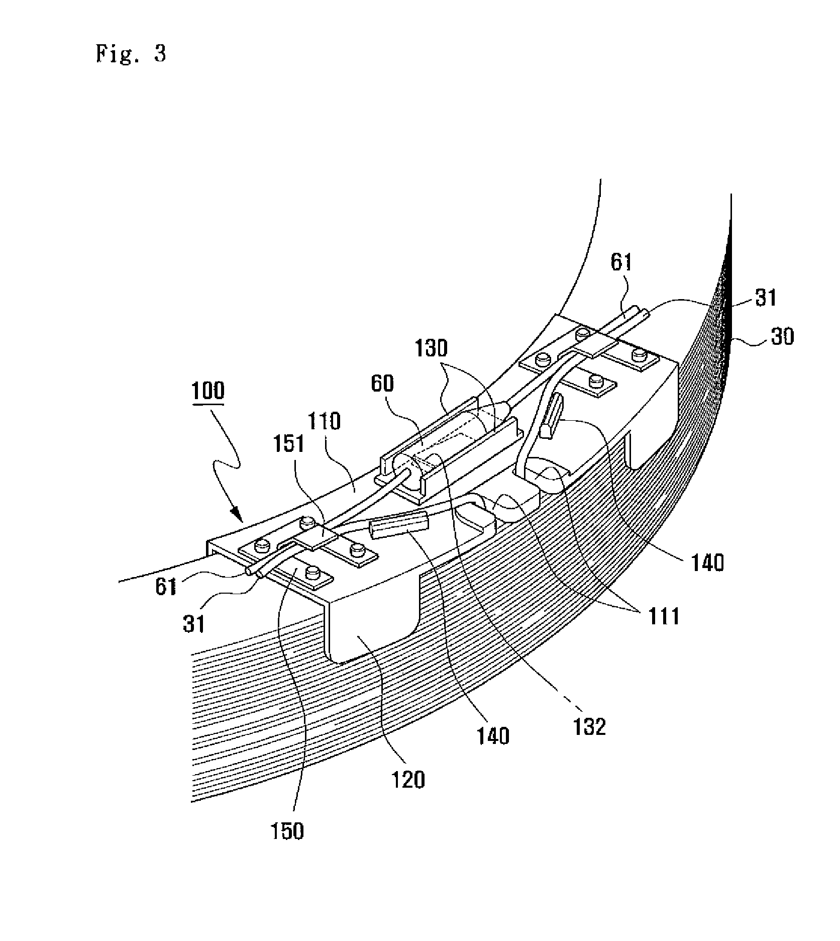
[0037]Hereinafter, preferred embodiments of a field coil assembly for an electromagnetic clutch according to the present invention will be described with reference to the accompanying drawings.

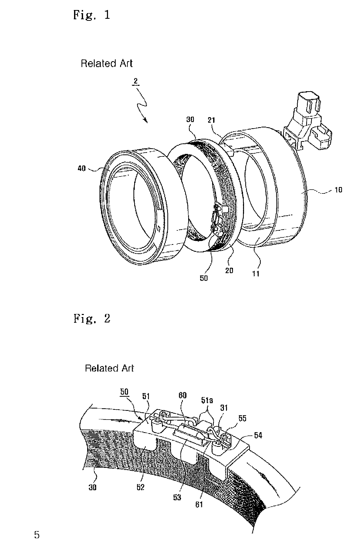
[0038]First, prior to the description of the present invention, throughout the drawings, the same reference numerals are used to designate the same elements as described in the prior art, and the overlapped descriptions will he omitted.

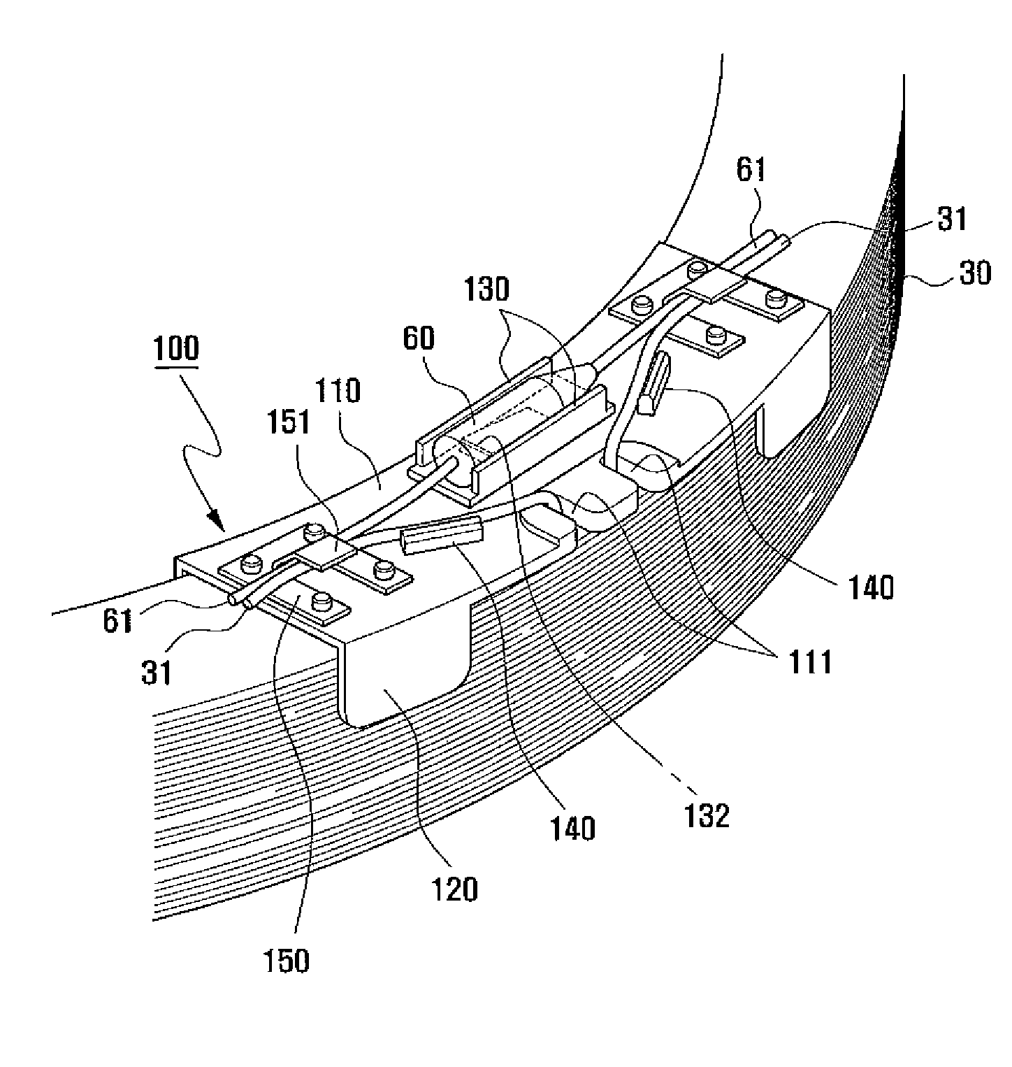
[0039]Referring to the figures, a field coil assembly 2 for an electromagnetic clutch according to the present invention includes an electromagnetic coil body 30 formed by winding an electromagnetic coil; a bobbin 20 for receiving and supporting the electromagnetic coil body 30 therein; a field core 10 for receiving the bobbin 20 to protect the bobbin 20 and the electromagnetic coil body 30; and an epoxy injection molded body 40 which is injected into the field core 10 to fill a space between the bobbin 20 and the field core 10 and to fix the bobbin 20 and the e...


PUM


Abstract

The present invention relates to a field coil assembly for an electromagnetic clutch, which comprises an electromagnetic coil body 30 formed by winding an electromagnetic coil; a bobbin 20 for supporting the electromagnetic coil body 30; a field core 10 for receiving the bobbin 20 and the electromagnetic coil body 30; a holder 100 mounted to the electromagnetic coil body 30; and a thermal fuse 60 installed to the holder 100 to be connected to the electromagnetic coil body 30, wherein the holder 100 having the thermal fuse 60 installed thereto is provided with an elastic member for elastically supporting the thermal fuse 60 upwards. Thus, the height of the thermal fuse 60 installed to the holder 100 can be adjusted.

Description

BACKGROUND OF THE INVENTION[0001]1. Field of the Invention[0002]The present invention relates to a field coil assembly for an electromagnetic clutch, and more particularly, to a field coil assembly for an electromagnetic clutch, wherein a thermal fuse is installed to a holder mounted to an electromagnetic coil body so that the height of the thermal fuse may be variably adjusted, thereby preventing damage in the thermal fuse which may be caused by a injection molding apparatus during an injection molding process.[0003]2. Description of the Related Art[0004]Generally, a field coil assembly for an electromagnetic clutch is an electric apparatus, in which when electric power is supplied, the electromagnetic induction of a wound coil in the field coil assembly causes a magnetic field to be generated and the magnetic force accordingly causes a disc of a pulley and a hub disc of a driving shaft of a compressor to be connected to each other, so that the electromagnetic clutch may cause the ...

Claims


Application Information

Patent Timeline
IPC IPC(8): F16D27/02H01F5/00
CPCF16D27/10F16D2027/001F16D2027/005H01F27/402H01F27/306H01F27/325F16D2250/00F16D27/00H02K1/06
Inventor OH, SUNG-TAEGCHO, SUNG-WON
Owner HANON SYST
Features
  • R&D
  • Intellectual Property
  • Life Sciences
  • Materials
  • Tech Scout
  • Unparalleled Data Quality
  • Higher Quality Content
  • 60% Fewer Hallucinations
Learn More