Device and method for processing backflushed fluid

Inactive Publication Date: 2009-02-26
BLANCO GMBH & CO KG +1
View PDF11 Cites 11 Cited by
  • Summary
  • Abstract
  • Description
  • Claims
  • Application Information

AI Technical Summary

Benefits of technology

[0030]Since the sediment collecting region is separated from the sedimentation container before the discharge of the sediment by means of the sluice mechanism, discharge

Problems solved by technology

Processing devices of this type have a high fluid loss and/or require auxiliary filter aids, s

Method used


Image

  • Device and method for processing backflushed fluid
  • Device and method for processing backflushed fluid
  • Device and method for processing backflushed fluid

Examples


Embodiment Construction

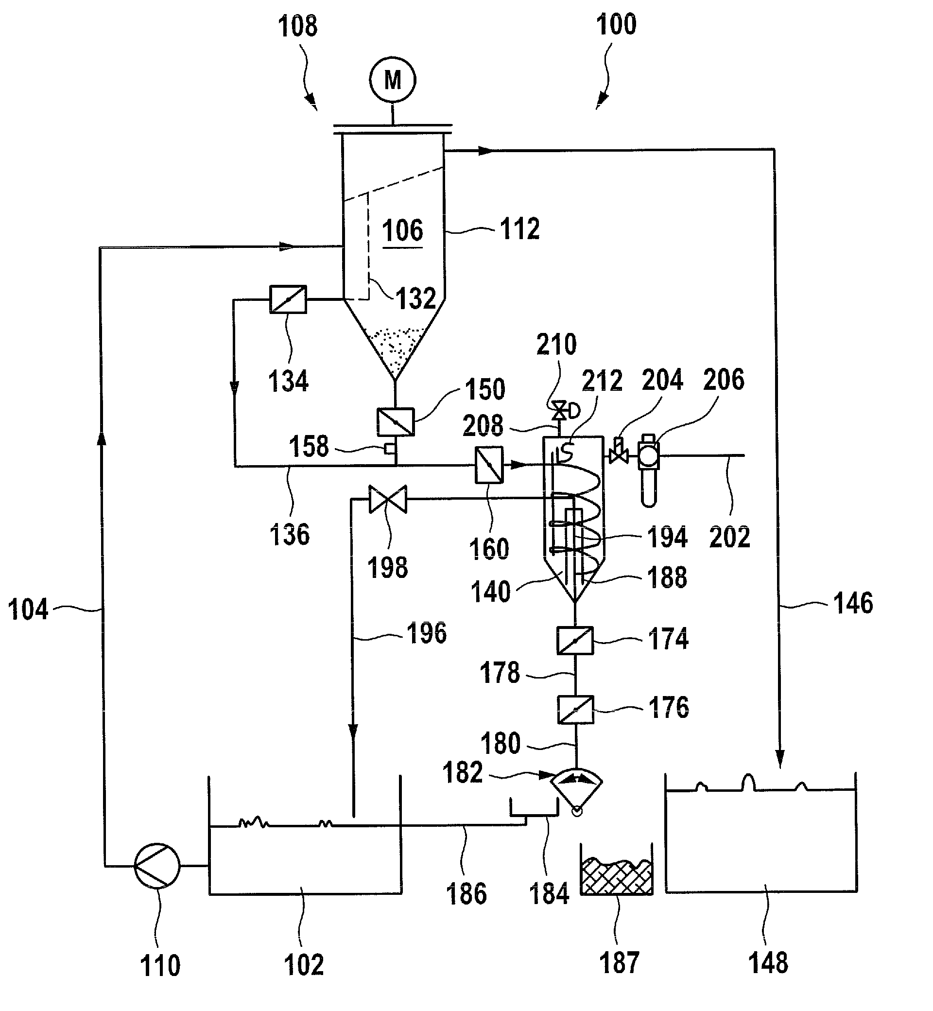
[0041]A filter device designated as a whole by 100 and shown in FIG. 1 to 7 for filtering a fluid medium containing solids, for example an aqueous cleaner, an oil or an emulsion, comprises a dirt tank 102 for receiving the medium to be filtered, which is connected to a dirt-side compartment 106 of a backflushing filter 108 by means of a filter supply line 104.

[0042]A filter pump 110 for conveying the medium to be filtered from the dirt tank 102 to the backflushing filter 108 is arranged in the filter supply line 104.

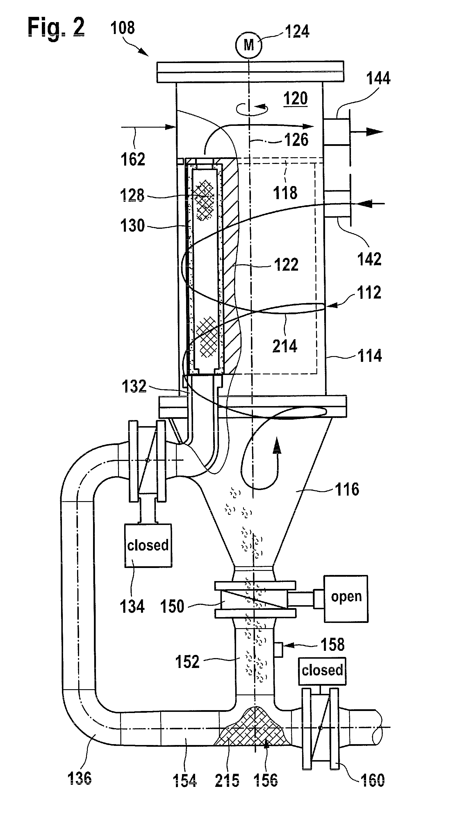
[0043]The structure of the backflushing filter 108 can be seen in detail from FIGS. 2 and 3.

[0044]The backflushing filter 108 comprises a filter housing 112 with a substantially cylindrical upper portion 114 and a lower portion 116, which tapers conically downwardly, adjoining the bottom of the upper portion 114.

[0045]The upper portion 114 of the filter housing 112 is separated by a horizontal partition 118 into a filtrate-side compartment 120 located above the partition...


PUM

PropertyMeasurementUnit
Pressureaaaaaaaaaa

Abstract

In order to provide a device for processing backflushed fluid from a backflushing filter containing solids, comprising a sedimentation device for separating solids from the backflushed fluid by sedimentation in a sediment collecting region, which device allows a discharge of solids without auxiliary filter agents, and has a fluid loss which is as low as possible, it is proposed that the sedimentation device should comprise a sluice mechanism, by means of which the sediment collecting region can be connected to a sedimentation container during a sedimentation phase and can be separated from the sedimentation container during a discharge phase and can be emptied.

Description

RELATED APPLICATION[0001]This application is a continuation application of PCT / EP2007 / 001570 filed Feb. 23, 2007, the entire specification of which is incorporated herein by reference.FIELD OF THE DISCLOSURE[0002]The present invention relates to a device for processing backflushed fluid from a backflushing filter, containing solids, the device comprising a sedimentation device for separating solids from the backflushed fluid by sedimentation in a sediment collecting region.BACKGROUND[0003]Devices for processing backflushed fluid from a backflushing filter are known from the prior art, in which the backflushed fluid of the backflushing filter is put into a processing basin or onto a band filter system. Processing devices of this type have a high fluid loss and / or require auxiliary filter aids, such as, for example, filter paper, to discharge the solids contained in the backflushed fluid.SUMMARY OF THE INVENTION[0004]The present invention is based on the object of providing a device f...

Claims


Application Information

Patent Timeline
IPC IPC(8): B01D21/24B01D29/66
CPCB01D21/0012B01D21/0024B01D21/2411B01D21/245B01D21/30B01D29/66B01D36/04B01D29/94B01D21/34
Inventor KASKE, EGON
Owner BLANCO GMBH & CO KG
Why Eureka
Try Eureka