Gamma camera including a scintillator and an image intensifier

Inactive Publication Date: 2009-02-26
THE ARIZONA BOARD OF REGENTS ON BEHALF OF THE UNIV OF ARIZONA
View PDF11 Cites 25 Cited by
  • Summary
  • Abstract
  • Description
  • Claims
  • Application Information

AI Technical Summary

Problems solved by technology

A fiber-optic taper that increases the field of view can be used to increase the active imaging area but at the expense of light intensity, thus making cluster detection difficult as well as imposing a limitation of the usable thickness of the scintillation crystal for gamma-ray detect

Method used


Image

  • Gamma camera including a scintillator and an image intensifier
  • Gamma camera including a scintillator and an image intensifier
  • Gamma camera including a scintillator and an image intensifier

Examples


Embodiment Construction

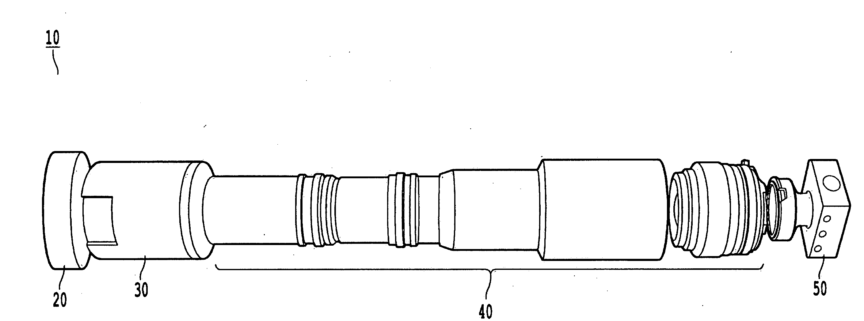
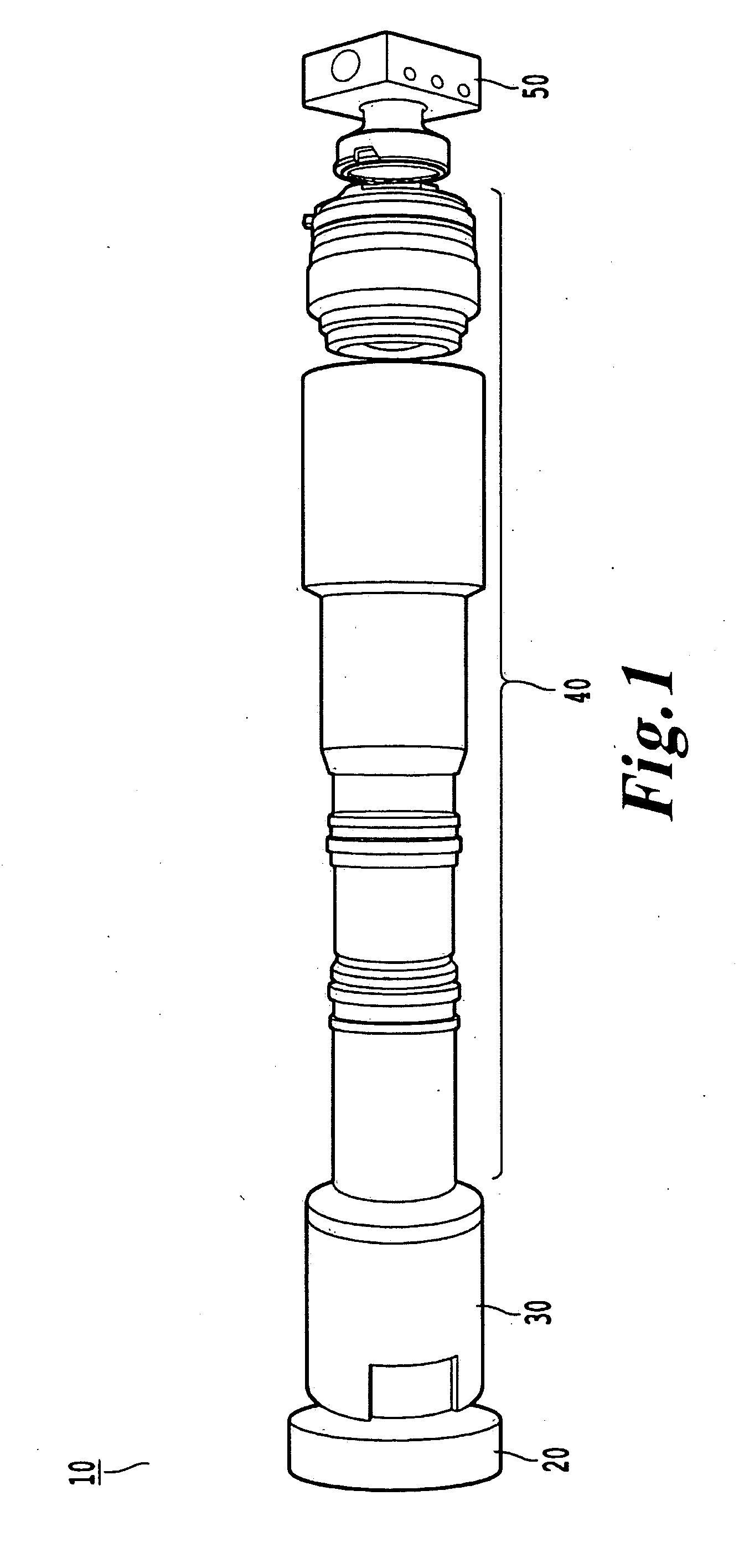
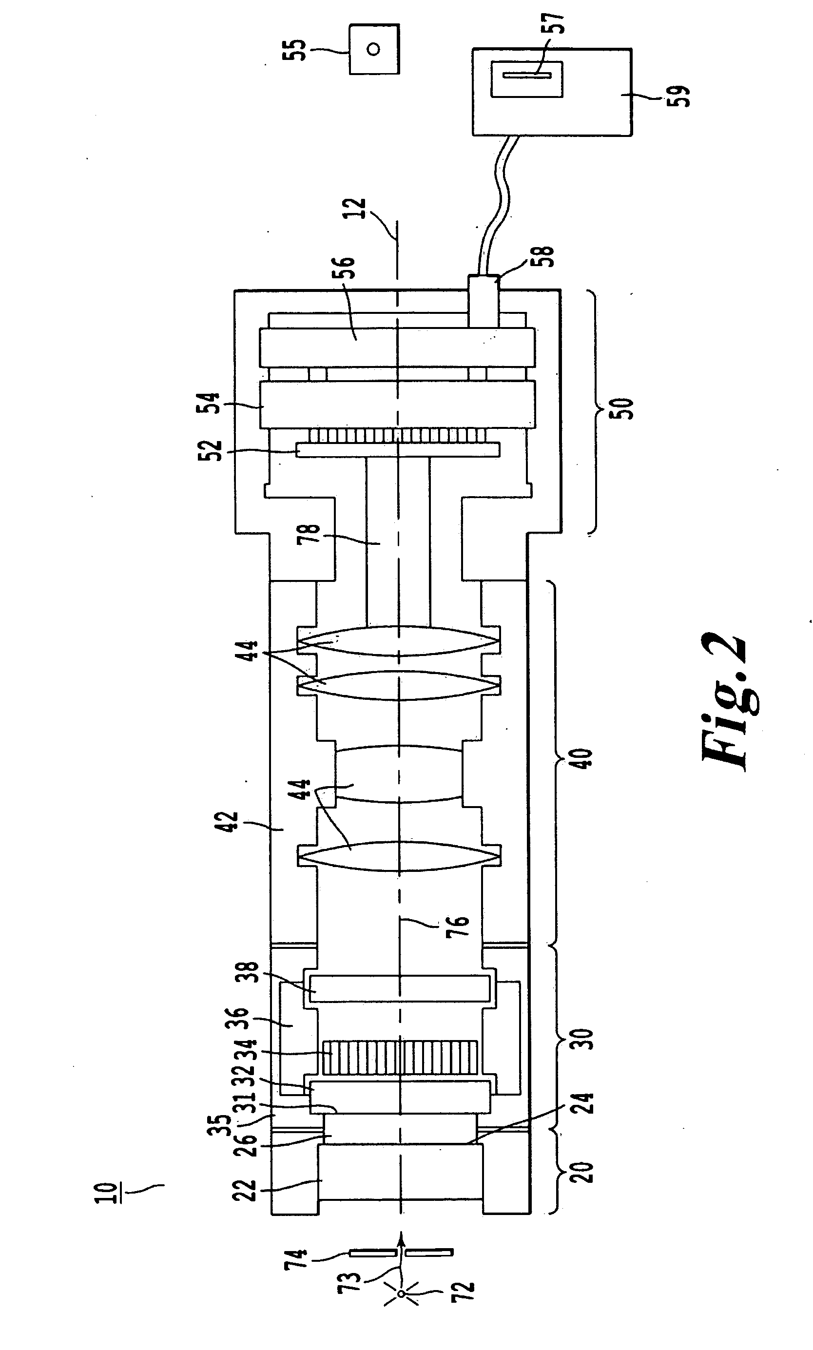
[0025]In accordance with the present invention, a gamma camera is schematically illustrated in FIG. 1, and is referred to throughout by reference numeral 10. First, a scintillator 20 is arranged that can convert the gamma rays or X rays from a corresponding source into optical radiation, such as visible light, to form a light emitting pattern or image on a rear surface of scintillator 20. Scintillator 20 is coupled to an image intensifier 30 that can amplify light emitted by scintillator 20. An interface between scintillator 20 and image intensifier 30 is arranged to minimize light loss and distortion between these two elements. After the image intensifier 30, an optical system 40 is arranged, for example an objective lens that can either magnify or minify an image formed by the amplified light. The image formed by the optical system 40 is then focused on an image sensor of a detector 50 that is connected to the optical system 40. The detector 50 is configured to read out a measurem...


PUM


Abstract

A gamma-ray or X-ray detection device including a scintillator configured to convert gamma rays or X-rays into optical radiation, an optical image intensifier configured to intensify the optical radiation to generate intensified optical radiation, an optical coupling system configured to guide the intensified optical radiation, and a solid state detector configured to detect the intensified optical radiation to generate an interaction image representing a gamma-ray or X-ray energy emission.

Description

CROSS REFERENCE TO RELATED PATENT DOCUMENTS[0001]The present patent application claims priority to the provisional Application with the Ser. No. 60 / 965,910 that was filed on Aug. 23, 2007 all the contents thereof being herewith incorporated by reference.BACKGROUND OF THE INVENTION[0002](a) Field of the Invention[0003]The present invention relates to a high-resolution, modular gamma or X-ray camera based on a scintillator and an image intensifier having a strong optical gain that are optically coupled to a solid state detector.[0004](b) Brief Description of the Related Art[0005]In the field of single photon emission computed tomography (SPECT) and molecular imaging, gamma-ray detectors with high spatial resolution are used. Currently, the high-resolution requirement for such systems can be satisfied by using a gamma-ray detector based on high-speed and low-noise charge coupled devices (CCD). Such detectors yield a spatial resolution that is sufficient to satisfy the high-resolution m...

Claims


Application Information

Patent Timeline
IPC IPC(8): G01T1/166G01T1/16
CPCG01T1/1642G01T1/1644A61B6/4258A61B6/037A61B6/508
Inventor BARRETT, HARRISON H.FURENLID, LARS R.BARBER, H. BRADFORDMILLER, BRIAN W.
Owner THE ARIZONA BOARD OF REGENTS ON BEHALF OF THE UNIV OF ARIZONA
Why Eureka
Try Eureka