
Dielectric resonator oscillator and radar system using the same

Inactive Publication Date: 2009-02-26
HITACHI LTD
View PDF3 Cites 2 Cited by
  • Summary
  • Abstract
  • Description
  • Claims
  • Application Information

AI Technical Summary

Benefits of technology

[0007]In a dielectric resonator oscillator used in a radar system or a communication system using a microwave or a millimeter wave, methods for improving a mass-production yield and reducing the production cost are strongly desired.
[0011]Furthermore, afore mentioned Japanese Patent Application Publication No. H08-293728 intends to reduce the cost by incorporating a tuning circuit into the interior of an MMIC and forming only a connecting line on a dielectric substrate. However, the document does not disclose a configuration of forming a DRO by mounting a dielectric resonator on a dielectric substrate.
[0012]An object of the present invention is to provide a dielectric resonator oscillator that can improve a mass-production yield and reduce the production cost, and a radar system using the dielectric resonator oscillator.
[0017]According to the preset invention, it is possible to provide a dielectric resonator oscillator and a radar system using the dielectric resonator oscillator that can improve a mass-production yield and reduce the production cost. BRIEF DESCRIPTION OF DRAWINGS

Problems solved by technology

In the case of the DRO shown in FIG. 11, it is necessary to use not only the MMIC chip 2 but also the dielectric substrate 25 and to form circuit parts such as the transmission line 8 and the terminating resistor and earthing means 9 on the dielectric substrate, and thus the problem here is that the production cost increases.
The resultant problems are that the area of the MMIC chip 2 increases and the production cost also increases.
A resultant problem is that the time required for the assembly work increases.
However, the document does not disclose a configuration of forming a DRO by mounting a dielectric resonator on a dielectric substrate.

Method used


Image

  • Dielectric resonator oscillator and radar system using the same
  • Dielectric resonator oscillator and radar system using the same
  • Dielectric resonator oscillator and radar system using the same

Examples


first embodiment

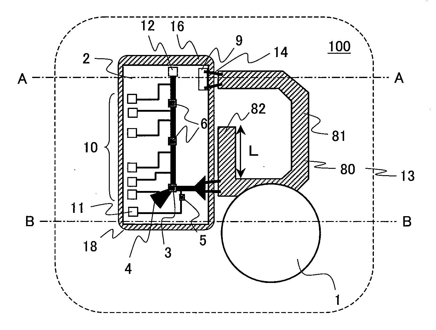
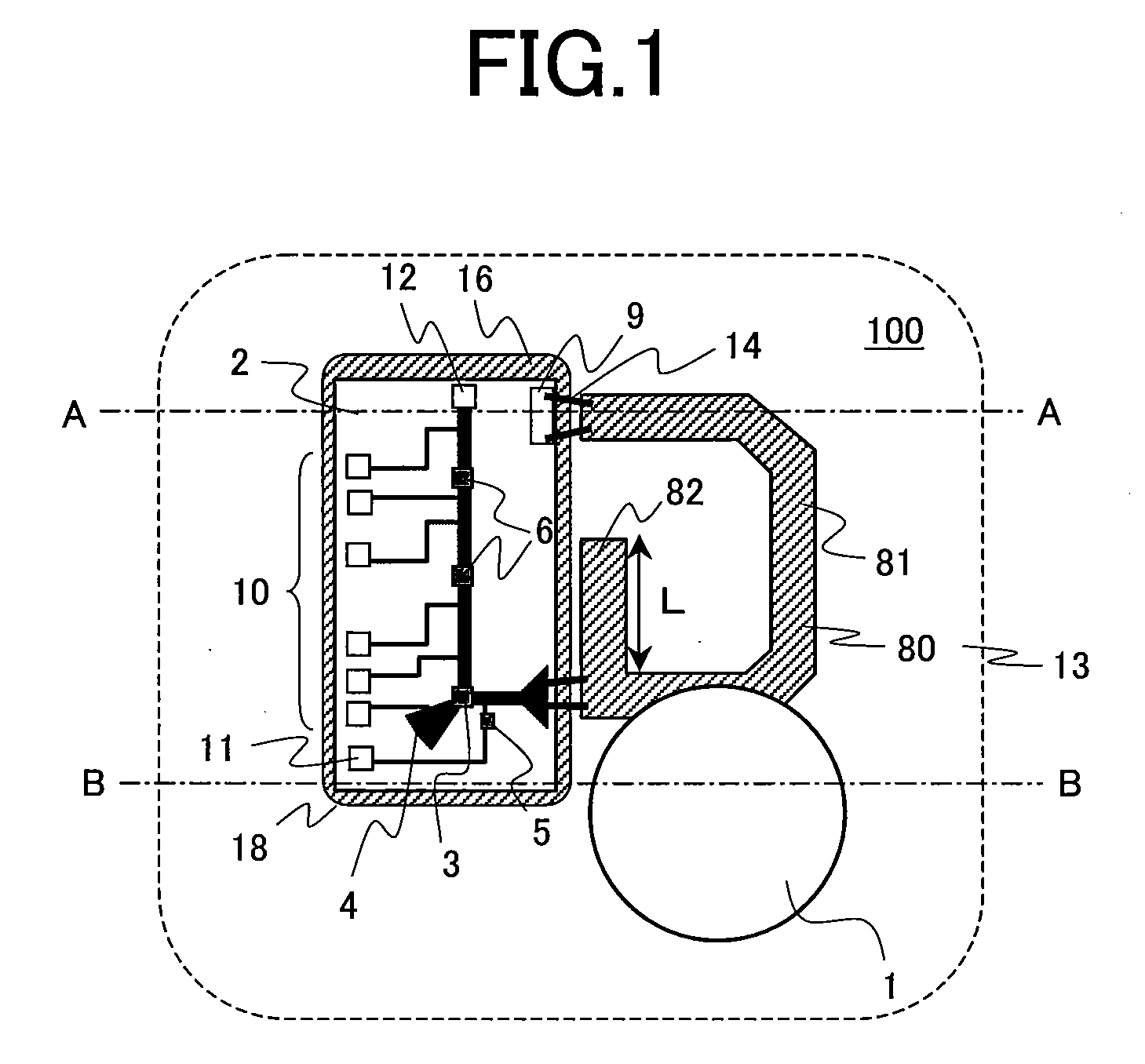
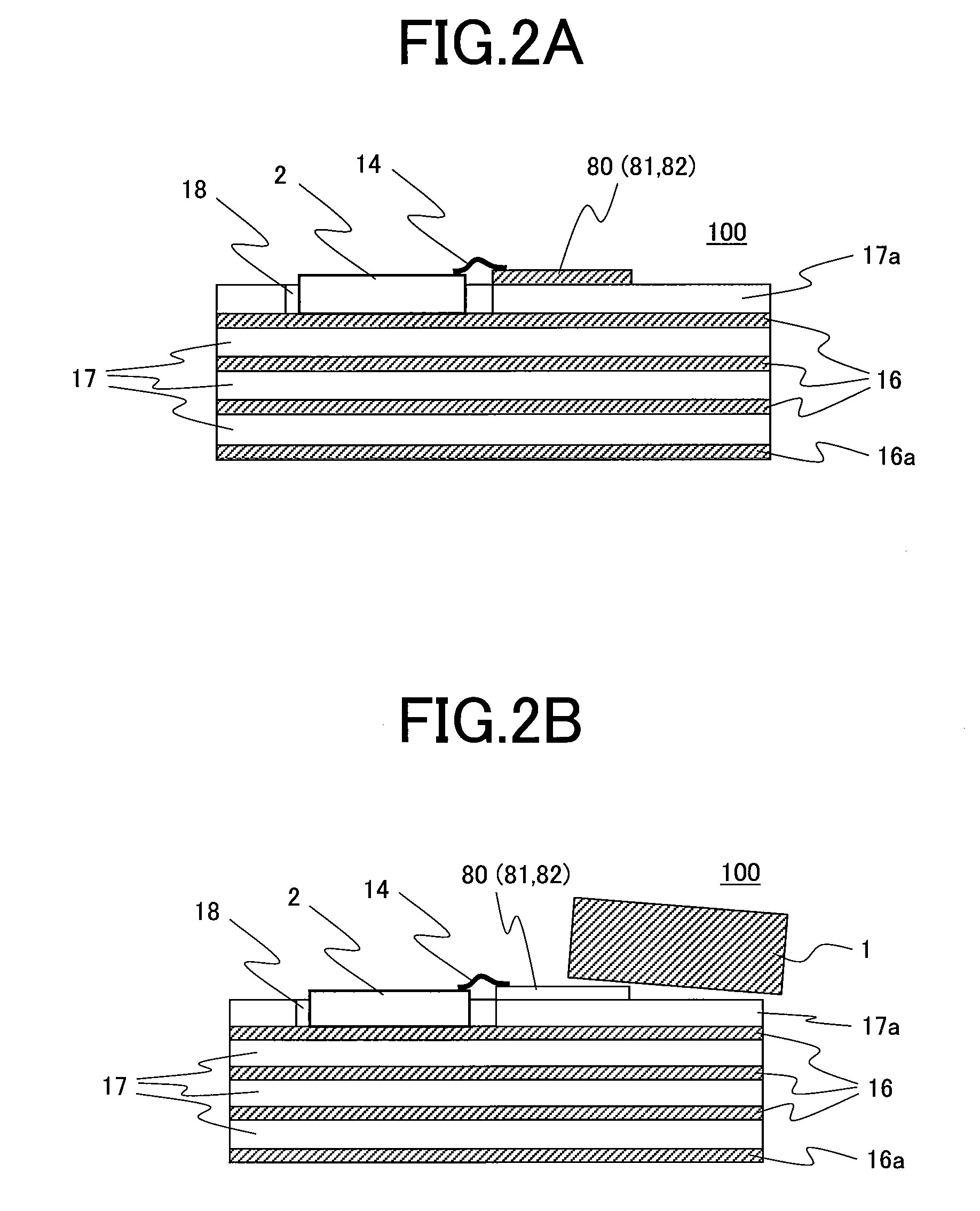
[0037]The first embodiment according to the present invention is explained in reference to FIGS. 1, 2A to 2D, and FIGS. 3A and 3B. FIG. 1 is a top view showing a dielectric resonator oscillator according to the first embodiment of the present invention. FIG. 2A is a sectional view taken on line A-A in FIG. 1. FIG. 2B is a sectional view taken on line B-B in FIG. 1. FIG. 2C is a view explaining the configuration of the first embodiment. FIG. 2D is a view explaining a modified example of the first embodiment.

[0038]In a dielectric resonator oscillator 100 according to the present embodiment, a dielectric resonator 1, an MMIC 2, and a transmission line 81 are formed on a common dielectric substrate 13. That is, on a multilayered dielectric substrate 13, a layered structure comprising a bottom conductive layer 16a, inner conductive layers 16, inner dielectric layers 17, and a top dielectric layer 17a, a columnar dielectric resonator 1, and an MMIC chip 2 are disposed. The multilayered di...

second embodiment

[0053]A dielectric resonator oscillator (DRO) 100 according to the first embodiment is used as a signal source of a radar module, a radar system, or a communication system using a microwave or a millimeter wave.

[0054]As the second embodiment according to the present invention, an example of a configuration of the case where the DRO 100 according to the first embodiment is applied to a radar system using a microwave or a millimeter wave is shown. FIG. 4 is a top view showing a transmitting and receiving module substrate comprising a transmitting and receiving module and a transmitting and receiving antenna and FIG. 5 is a circuit block diagram thereof.

[0055]As a transmitting and receiving module 200 for a radar system, a power amplifier MMIC 2a to amplify transmitting signals and two units of receivers MMICs 2b to mix receiving signals with local signals and generate IF signals are mounted on the multilayered dielectric substrate 13 as a shared ceramic substrate in addition to the DR...

third embodiment

[0060]Successively, as the third embodiment of the present invention, an example of concrete procedure in the case where the DROs 100 according to the first embodiment are produced in quantities is explained in reference to FIGS. 6 to 8. FIG. 6 is a graph showing the correlation between an open stub length L and an oscillating output power Pout in consideration of the difference between individual DROs and FIG. 7 is a graph similarly showing the correlation between an open stub length L and an oscillating frequency fosc . Further, FIG. 8 shows an assembly flow at the mass production of DROs.

[0061]The correlations of the oscillating output power Pout and the oscillating frequency fosc with the open stub length L vary in ranges in accordance with individual DROs as shown in FIGS. 6 and 7, reflecting the difference in the positions of dielectric resonators, the difference in the characteristics of MMICs, the difference in the length of wires, and others among the components of the DROs...


PUM


Abstract

In the mass production of dielectric resonator oscillators (DROs), it is necessary to regulate the position where a dielectric resonator is placed with a high degree of accuracy and thus time required for the assembly work increases undesirably. Further, a terminating resistor and earthing means are formed at an end of a transmission line that is electromagnetically coupled to the dielectric resonator and constitutes the resonator on a dielectric substrate, and as a result the production cost increases. The present invention is characterized in that, in the components of a DOR, only a transmission line is formed on a dielectric substrate, and an oscillating active element and a terminating resistor and the earthing means on an MMIC chip are connected to the transmission line with metallic wires, metallic ribbons, or the like. Further, an open stub is formed in the middle of the transmission line on the side close to the oscillating active element when it is viewed from the dielectric resonator.

Description

CLAIM OF PRIORITY[0001]The present application claims priority from Japanese application JP 2007-160139 filed on Jun. 18, 2007, the content of which is hereby incorporated by reference into this application.FIELD OF THE INVENTION[0002]The present invention relates to a dielectric resonator oscillator used in a radar system or a communication system using a microwave or a millimeter wave, and a radar system or a communication system that uses the dielectric resonator oscillator.BACKGROUND OF THE INVENTION[0003]As a dielectric resonator oscillator (DRO) used in a radar system or a communication system using a microwave or a millimeter wave, a device disclosed in U.S. 2003 / 0048217 A1 (Japanese Patent Application Laid-Open Publication No. 2003-84058) is known for example. FIG. 11 shows a first example of the DRO disclosed in the document. A dielectric substrate 25 is disposed adjacently to an MMIC (Microwave Monolithic IC) chip 2, and a transmission line 8 and a terminating resistor and...

Claims


Application Information

Patent Timeline
IPC IPC(8): H03B5/18G01S13/00
CPCH03B5/1876H03B2200/0028H03B2200/0022
Inventor KURITA, NAOYUKIMATSUURA, KAZUO
Owner HITACHI LTD
Learn More