Imaging Apparatus and Drive Recorder System

a drive recorder and image resolution technology, applied in the field of image resolution and drive recorder system, can solve the problem of insufficient image resolution to analyze a pictur

Inactive Publication Date: 2009-02-26
NIKON CORP
View PDF14 Cites 27 Cited by
  • Summary
  • Abstract
  • Description
  • Claims
  • Application Information

AI Technical Summary

Benefits of technology

[0016]According to the present invention, the image processing section generates accident image data representing an accident situation at an accident occurrence in a manner different from that in a normal situation, and a detailed situation at the accident can be analyzed using this accident image data.

Problems solved by technology

However, while an outline of a process until an accident occurrence can be grasped with aforementioned moving image data, there are many cases where an image resolution is not high enough to analyze a picture at an accident in detail.

Method used


Image

  • Imaging Apparatus and Drive Recorder System
  • Imaging Apparatus and Drive Recorder System
  • Imaging Apparatus and Drive Recorder System

Examples


first embodiment

Description of a First Embodiment

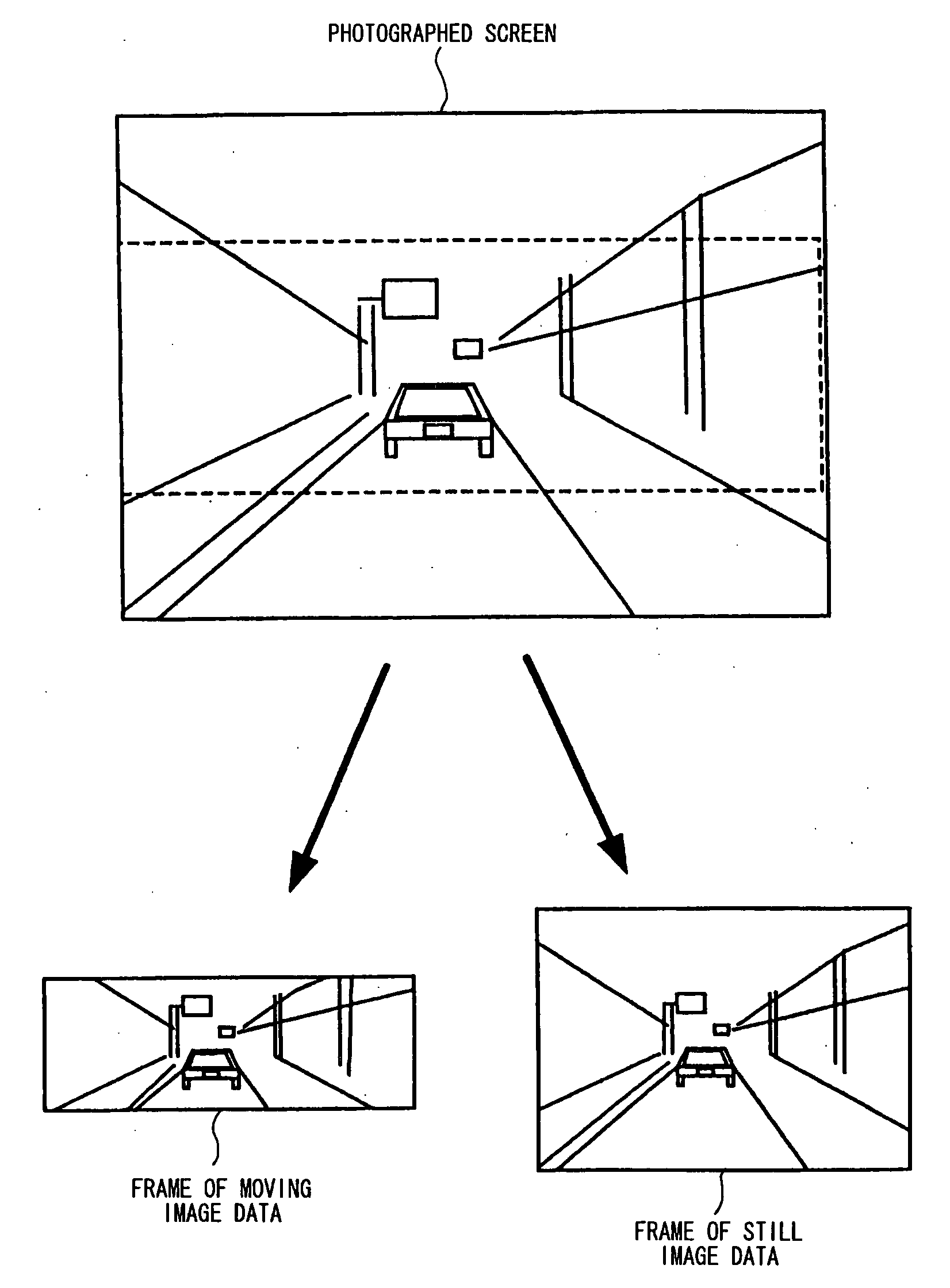
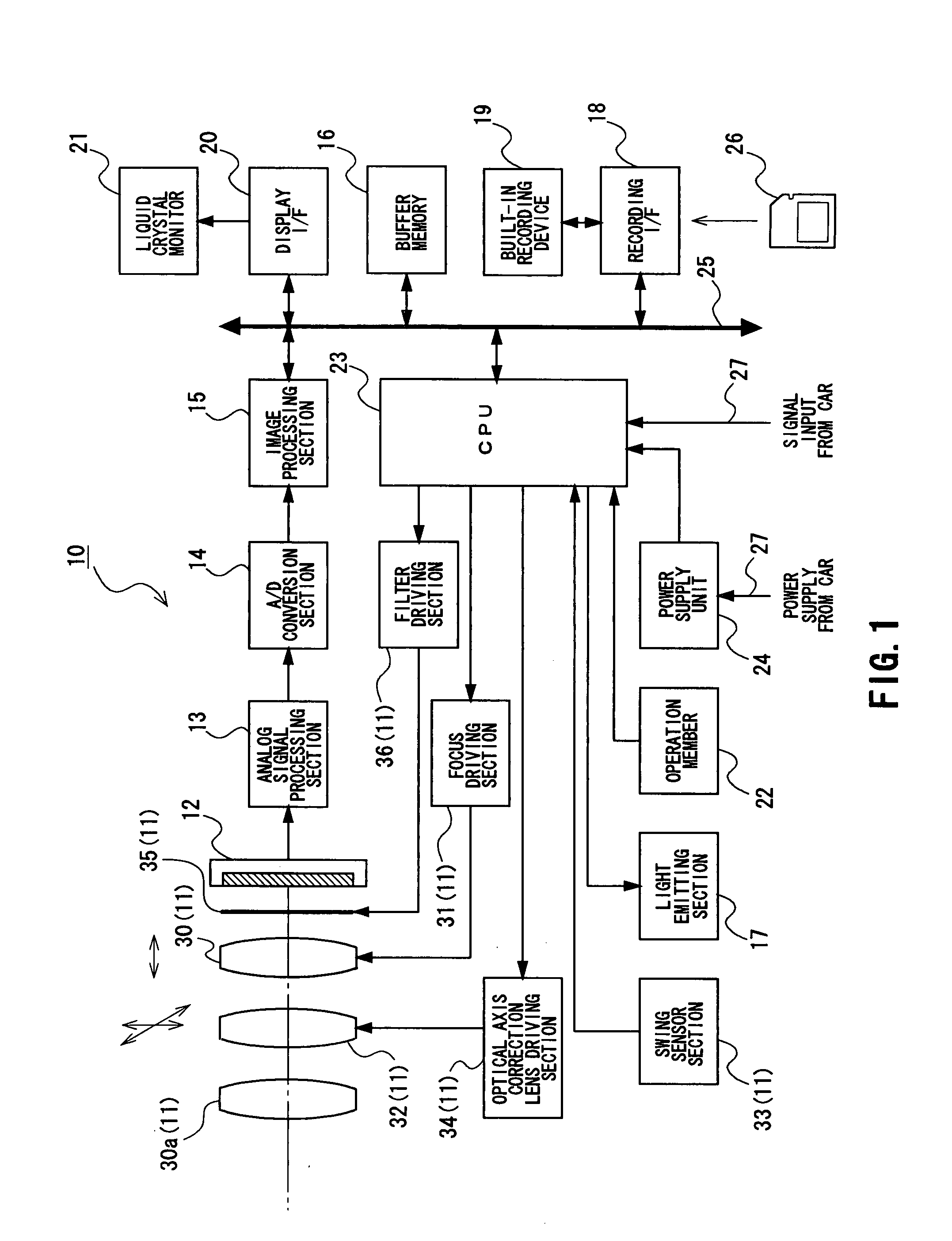
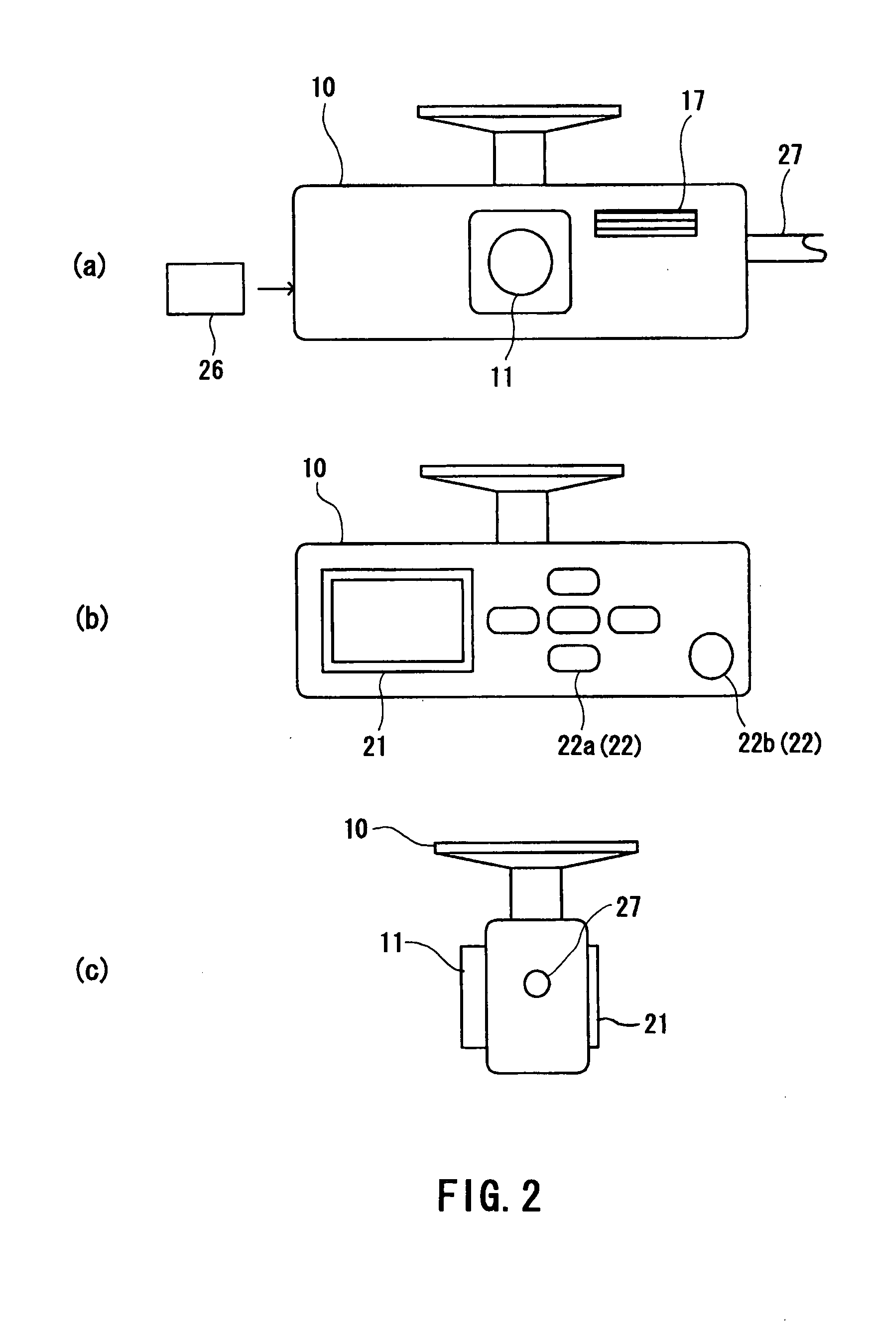
[0028]FIG. 1 is a block diagram showing a configuration of a drive recorder camera according to a first embodiment. FIG. 2 is an appearance view of the drive recorder camera and FIG. 3 is a diagram showing an attached state of the drive recorder camera.

[0029]A drive recorder camera 10 according to the first embodiment is attached to a position in a car, from which an area including a viewing field ahead of a driver's seat can be photographed, (for example, near a rearview mirror in the car). Then, the drive recorder camera 10 can photograph an image around the car during car driving (refer to FIG. 3). As shown in FIG. 2A, a photographic optical system 11 and a light emitting section 17 are disposed on the front side of a housing of the drive recorder camera 10. Also, as shown in FIG. 2B, a liquid crystal monitor 21, and an operation switch 22a and a release button 22b forming an operation member 22 are disposed on the rear side of the housing of the ...

second embodiment

Description of a Second Embodiment

[0070]FIG. 8 is a timing chart of photographing a still image in a second embodiment. Here, in the embodiment described below, the same constituents as in the first embodiment are denoted by the same symbols and duplicated explanations will be omitted.

[0071]The second embodiment is a variation of the first embodiment, and a CPU 23 carries out photographing a moving image for a predetermined time period just after an accident occurrence, and carries out photographing a still image in multiple times after having finished photographing a moving image.

[0072]In this second embodiment, in addition to almost the same advantages as in the first embodiment, it is possible to obtain moving image data in which motions of an object are more natural, since photographing of a moving image is not interrupted by photographing of a still image.

third embodiment

Description of a Third Embodiment

[0073]FIG. 9 is a flow chart showing operation of a drive recorder camera according to a third embodiment. This third embodiment has a configuration in which accident image data starts to be generated in advance at a sudden braking. Here, S201 and S202 in FIG. 9 correspond to S101 and S102 in FIG. 5, S207 to S 210 in FIG. 9 correspond to S103 to S106, respectively, and explanation thereof will be omitted.

[0074]Step S203: A CPU 23 determines whether a car has braked suddenly or not. More specifically, the CPU 23 determines that a car has braked suddenly (1) in a case where a braking signal is input into the CPU 23 from the car and a swing value larger than a threshold value is detected at the same time from a swing sensor section 33, (2) in a case where an output pattern from the swing sensor section 33 corresponds to a pattern which was experimentally obtained for a sudden braking, or the like. Then, if there is a sudden braking (YES), the process go...


PUM


Abstract

An imaging apparatus mounted on a vehicle and imaging a vicinity of the vehicle, includes a photographic lens, an image pickup device, an image processing section, an accident detection sensor, a controlling section, and a recording section. The image pickup device generates an image signal by performing photoelectric conversion of an object image based on a light flux from the photographic lens. The image processing section generates moving image data during vehicle driving based on an image signal. The accident detection sensor detects an accident occurrence based on a shock to the vehicle. The controlling section makes the image processing section generate accident image data representing an accident situation based on an output of the accident detection sensor in a manner different from that in a normal situation. Then, the accident image data is recorded in the recording section.

Description

TECHNICAL FIELD[0001]The present invention relates to an imaging apparatus and a drive recorder system mounted on a vehicle for imaging and recording a vicinity of the vehicle at an accident.BACKGROUND ART[0002]Conventionally, there are proposed drive recorders which mount cameras capable of photographing moving images on vehicles and record pictures at accidents (refer to Patent Document 1 and Non-patent Document 1). These drive recorders have a configuration in which moving image data is generated by imaging a vicinity of the vehicle during driving and moving image data in a recording section is overwritten and updated sequentially in a normal situation. Then, when an accident has occurred, overwriting of moving image data in the recording section is forbidden and moving image data for a certain period of time before and after the accident is held in the recording section. Here, from a requirement that moving image data for a long time is to be recorded with a small recording capa...

Claims


Application Information

Patent Timeline
Patent Type & Authority Applications(United States)
IPC IPC(8): B60Q1/00H04N7/18
CPCB60R1/00B60R11/04B60R2300/302B60R2300/304B60R2300/8026B60R2300/8033H04N5/907B62D41/00G07C5/0891H04N5/232H04N5/23245H04N5/77B60R2300/8093H04N23/667
Inventor FUJINAWA, NOBUHIRONOZAKI, HIROTAKEMITSUHASHI, SETSU
Owner NIKON CORP
Why Eureka
Try Eureka