
Flicker correcting method, flicker correcting circuit, and imaging device using them

a flicker correction and flicker technology, applied in the field of flicker correction methods and flicker correction circuits, to achieve the effect of reliably and accurately reducing the contingency of flicker components and reducing the contained flicker components

Inactive Publication Date: 2009-02-26
SONY CORP
View PDF10 Cites 18 Cited by
  • Summary
  • Abstract
  • Description
  • Claims
  • Application Information

AI Technical Summary

Benefits of technology

[0019]In view of the above-identified circumstances, it is the object of the present invention to provide a flicker correction method that can reliably and accurately reduce the flicker component contained in a video signal when the video signal is any of various video signals having different respective frame periods or some other specific periods or when the flicker component contained in the video signal is any of various flicker components having different respective repetition periods, a flicker correction circuit adapted to use such a method and also an image pickup apparatus realized by employing such a flicker correction method and such a flicker correction circuit.
[0023]Thus, according to the present invention as defined above, a flicker correction signal and a video signal of a specific period are subjected to an arithmetic process so that the flicker correction signal reduces the correction error of the flicker component of the video signal when forming a corrected video signal for the specific period for which the flicker component is corrected. Thus, it is possible to obtain a corrected video signal from which the flicker component is effectively reduced and reliably and accurately reduce the flicker component contained in a video signal when the video signal is any of various video signals having different respective frame periods or some other specific periods or when the flicker component contained in the video signal is any of various flicker components having different respective repetition periods.

Problems solved by technology

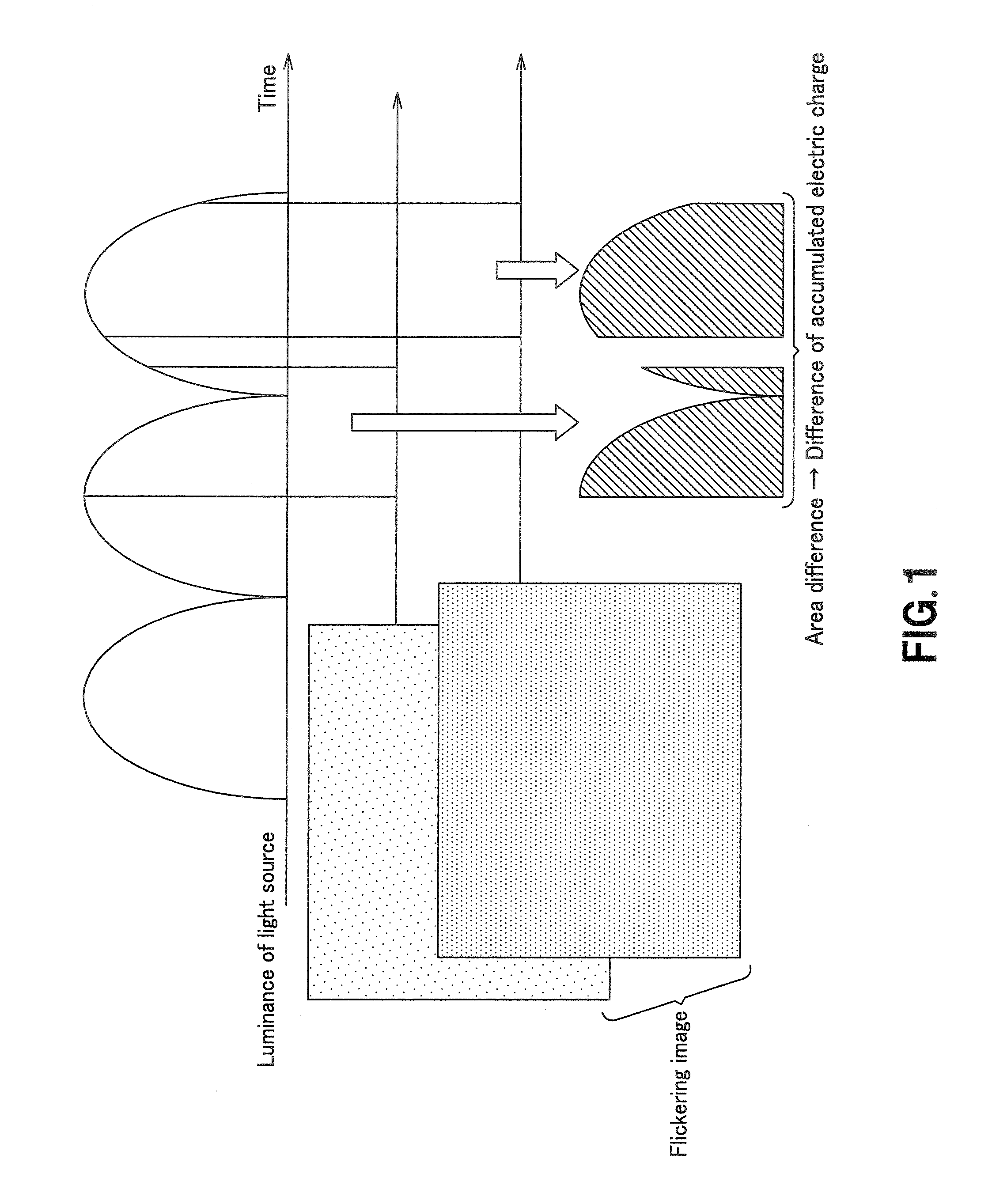
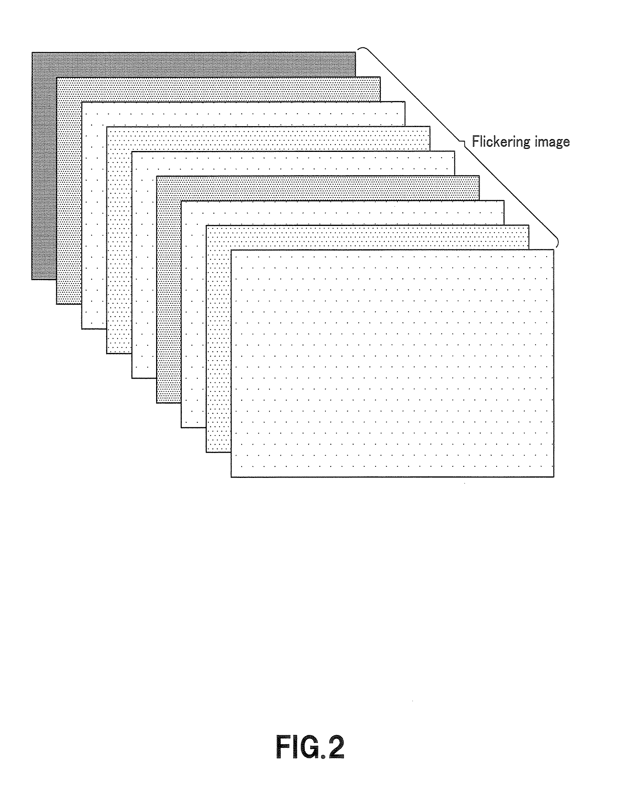
This is a phenomenon called flicker, which constitutes an inevitable problem when an image is picked up by an image pickup apparatus comprising an image sensor adapted to pick up an image with shifted timings of accumulating electric charges under a flickering light source.

Method used


Image

  • Flicker correcting method, flicker correcting circuit, and imaging device using them
  • Flicker correcting method, flicker correcting circuit, and imaging device using them
  • Flicker correcting method, flicker correcting circuit, and imaging device using them

Examples


Embodiment Construction

[0039]Now, the present invention will be described in greater detail by referring to the accompanying drawings that illustrate preferred embodiments of the present invention. Note, however, the present invention is by no means limited to the embodiments described below, which may be modified in various different ways without departing from the spirit and scope of the invention.

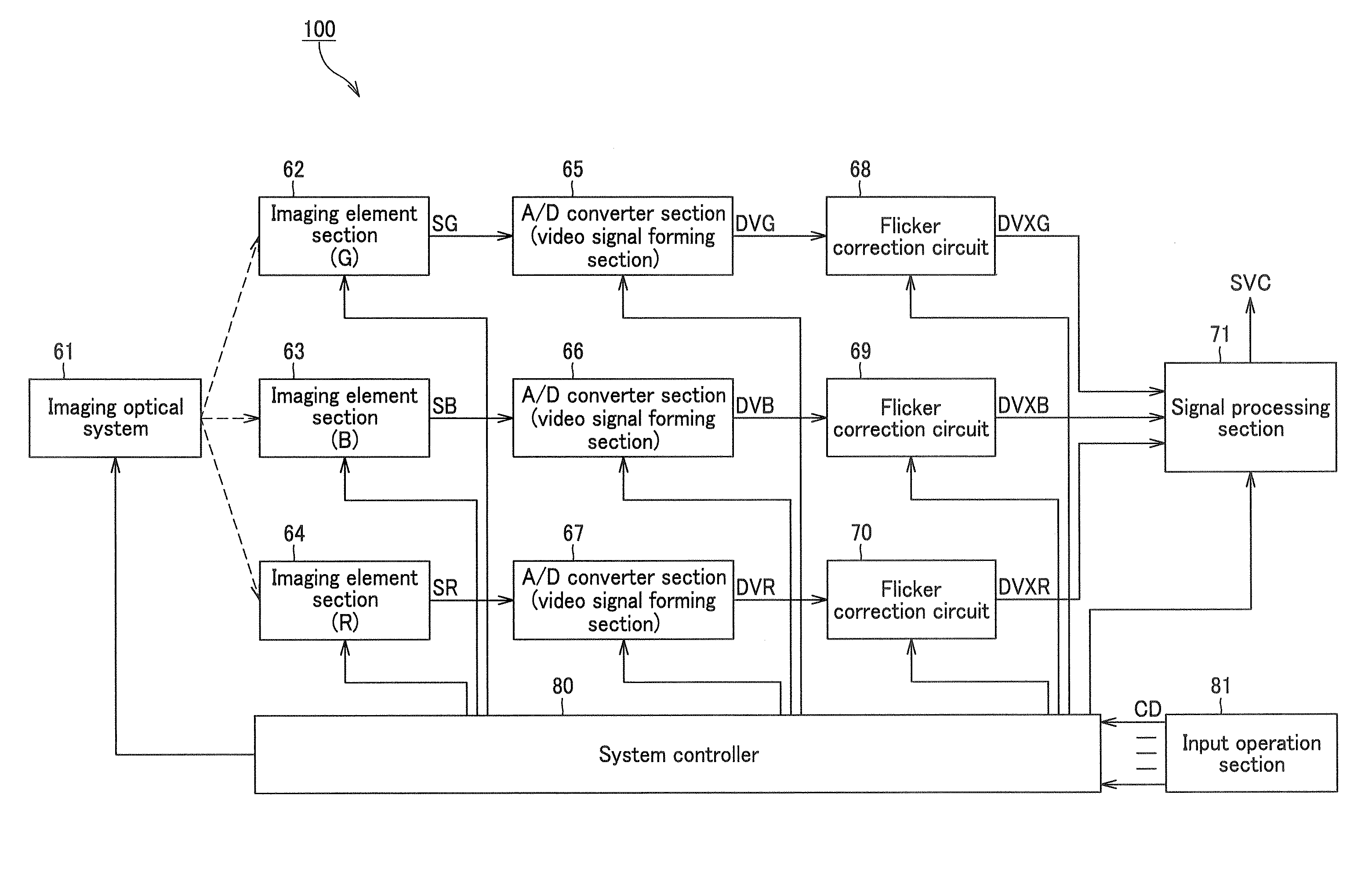
[0040]A flicker correction method according to the invention is embodied typically by means of a flicker correction circuit having a configuration as illustrated in FIG. 5.

[0041]FIG. 5 is a schematic block diagram of an embodiment of flicker correction circuit 12 according to the present invention, which also shows a video signal generating section 11 connected to it.

[0042]In the embodiment of FIG. 5, the video signal generating section 11 that typically includes an image pickup apparatus such as a color video camera sends out digital video signal DV, which is formed as a succession of frame periods and contai...


PUM


Abstract

An arithmetic processing section executes an arithmetic process on a flicker correction signal output from a flicker correction signal outputting section and corresponding to the flicker component contained in a video signal of each of specific periods and the video signal of each of the specific periods to form a corrected video signal of the specific period corrected for the flicker component of the specific period for the video signal of each of the specific periods formed as a succession of specific periods and containing a flicker component as supplied from a video signal generating section in response to a correction error signal of each of the specific periods supplied from a correction error detecting section.

Description

TECHNICAL FIELD[0001]This invention relates to a flicker correction method and a flicker correction circuit for correcting a video signal containing a flicker component to reduce the flicker component and also to an image pickup apparatus employing such a flicker correction method and such a flicker correction circuit.[0002]This application is based upon and claims the benefit of priority from the prior Japanese Patent Application No. 2004-330299, filed on Nov. 15, 2004, the entire contents of which are incorporated herein by reference.BACKGROUND ART[0003]Image pickup apparatus (video cameras) comprising an imaging signal generating section adapted to generate imaging output signals corresponding to the image of a subject obtained by way of an optical system that contains a solid-state imaging element and acquire video signals representing the image of the subject according to the imaging output signals have been and being popularly marketed. The solid-state imaging element containe...

Claims


Application Information

Patent Timeline
IPC IPC(8): H04N9/73H04N7/01H04N5/217H04N5/21H04N5/235
CPCH04N5/235H04N7/0132H04N5/2357H04N23/70H04N23/745H04N25/60
Inventor ONO, NORIYUKINAKASUZI, MOTOHIRONISHIDE, YOSHIAKIIKEYAMA, HIROMASASUDO, FUMIHIKO
Owner SONY CORP
Learn More