
High Power LED Lamp

a technology of led lamps and led lamps, applied in the field of led lamps, can solve the problems of large amount of heat, led lamps are damaged, led lamps cannot achieve the brightness desired, etc., and achieve the effects of high brightness, high power led, and good heat dissipation

Inactive Publication Date: 2009-02-26
XUE XINSHEN
View PDF8 Cites 87 Cited by
  • Summary
  • Abstract
  • Description
  • Claims
  • Application Information

AI Technical Summary

Benefits of technology

[0006]A primary object of the present invention is to provide a high power LED lamp which has good heat dispersion and high brightness.
[0017]In accordance with the present invention, a heat sink device is disposed between the cover and the substrate and the power supply, the insulator and the LED are combined together, so that the heat created during work of the LED can be radiated rapidly via the heat sink device and thus ensuring good heat dispersion, high brightness, long life and low temperature.

Problems solved by technology

However, a chip of a high power LED will create a large amount of heat.
If the heat cannot be radiated away in time, the LED will be damaged.
Because of the poor power supply, the LED lamp cannot achieve desired brightness.
Unfortunately, it has a very complex structure to bring inconvenience to manufacture and to result in high cost.

Method used


Image

  • High Power LED Lamp
  • High Power LED Lamp
  • High Power LED Lamp

Examples


first embodiment

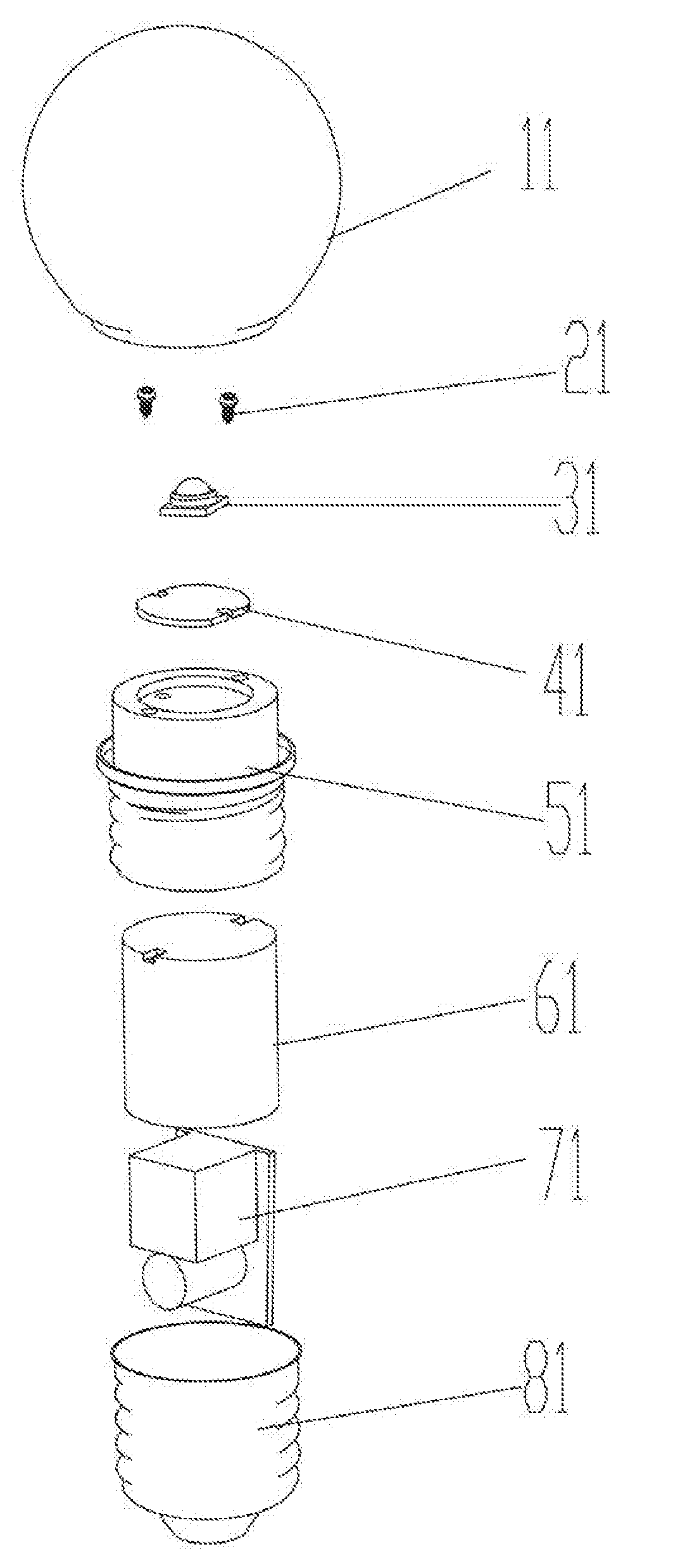
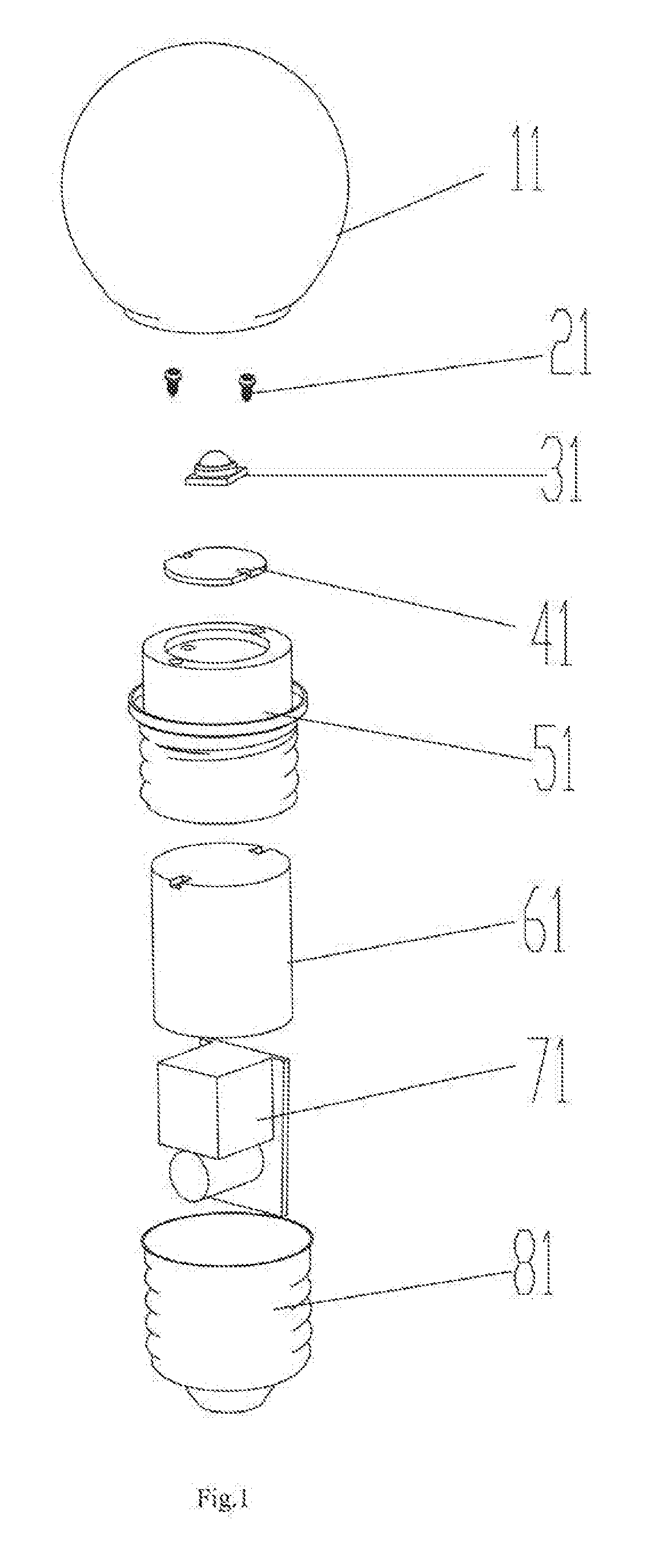
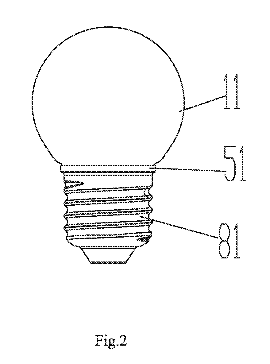
[0023]Referring to FIG. 1 and FIG. 2, in the present invention, a high power LED lamp includes a cover 11, an LED 31, a base panel 41, a power supply 71, a substrate 81 and a heat sink device 51. The heat sink device 51 is defined between the cover 11 and the substrate 81. The LED 31 is formed on the base panel 41. The LED 31 further includes an insulator 61 engaged with the heat sink device 51. In this embodiment, the insulator 61 is received in the heat sink device 51 and the power supply 71 is defined in the insulator 61. Both the LED 31 and the base panel 41 are arranged above the heat sink device 51.

[0024]In this embodiment the power supply 71 is a switching power supply which can directly connect to commercial power, so as to overcome the shortcoming of poor brightness caused by the low power supply.

[0025]The heat sink device 51 is made of aluminum, copper, iron, graphite or other materials having good heat dispersion. The heat sink device 51 is a hollow column and a projectin...

second embodiment

[0028]Referring to FIG. 3 and FIG. 4, in the present invention, a high power LED lamp includes a cover 12, an LED 32, a base panel 42, a power supply 62, a substrate 82 and a heat sink device 52. The heat sink device 52 is defined between the cover 12 and the substrate 82. The LED 32 is formed on the base panel 42. The LED 32 further includes an insulator 72 engaged with the heat sink device 52. In this embodiment, the insulator 72 is disposed under the heat sink device 52 and is fastened or adhered thereto. The power supply 62 is defined in the insulator 72. Both the LED 32 and the base panel 42 are arranged above the heat sink device 52.

[0029]In this embodiment the power supply 62 is a switching power supply which can directly connect to commercial power, so as to overcome the shortcoming of poor brightness caused by the low power supply.

[0030]The heat sink device 52 is made of aluminum, copper, iron, graphite or other materials having good heat dispersion. The heat sink device 52...


PUM


Abstract

A high power LED lamp comprises a cover; a base panel; an LED mounted on the base panel which further includes an insulator; a substrate; a power supply received in the insulator; and a heat sink device disposed between the cover and substrate; wherein the insulator is engaged with the heat sink device, and both the LED and base panel are defined above the heat sink device. In accordance with the present invention, the heat created during work of the LED can be radiated rapidly via the heat sink device and thus ensuring good heat dispersion, high brightness, long life and low temperature.

Description

BACKGROUND OF THE INVENTION[0001]1. Field of the Invention[0002]The present invention relates to an LED lamp and more especially to a high power LED lamp.[0003]2. Description of the Prior Art[0004]LED lamps have advantages of long life, energy saving, little electricity consumption, low work voltage and good security which are used to replace conventional incandescent lamps and energy-saving lamps. The known LED lamps are designed to combine a plurality of LEDs with aid of a reflector panel to increase brightness. However, a chip of a high power LED will create a large amount of heat. The higher the power is, the larger the heat is created. If the heat cannot be radiated away in time, the LED will be damaged. Thus, the LED lamp in practice is subject to a heat radiation limit and then adopt a low supply current, other than a switching supply. Because of the poor power supply, the LED lamp cannot achieve desired brightness. It appears that how to radiate the heat is the key factor to...

Claims


Application Information

Patent Timeline
IPC IPC(8): F21V29/00
CPCF21Y2101/02F21V3/00F21V17/10F21V29/89F21V29/20F21K9/135F21V23/023F21K9/232F21Y2115/10
Inventor XUE, XINSHEN
Owner XUE XINSHEN
Learn More