Thermocouple

a technology of thermocouples and junction beads, which is applied in the direction of heat measurement, process and machine control, instruments, etc., can solve the problems of junction beads deformation, affecting the uniformity of the resulting structure on the surface of the substrate, and unusable areas on the surface of finished substrates, so as to reduce the amount of temperature measurement. the effect of dri

Inactive Publication Date: 2009-02-26
ASM IP HLDG BV
View PDF99 Cites 322 Cited by
  • Summary
  • Abstract
  • Description
  • Claims
  • Application Information

AI Technical Summary

Benefits of technology

[0008]A need exists for a thermocouple that reduces the amount of drift of the temperature measurement resulting from deformation of the junction of the wires within the measuring tip of the sheath. In one aspect of the present invention, a temperature control system for a chemical vapor reactor is provided. The control system includes at least one heating element for providing radiant heat to the reactor. The control system further includes at least one temperature sensor for providing a temperature measurement at a position adjacent to a substrate being processed within the reactor. The temperature sensor includes a vertically oriented sheath having a measuring tip, a support tube disposed within the sheath, first and second wires disposed within the support tube, and a junction formed betwe

Problems solved by technology

If the temperature varies greatly across the surface of the substrate, the deposited layer could be uneven which may result in unusable areas on the surface of the finished substrate.
Similarly, non-uniformity or instability of temperatures across a substrate during other thermal treatments can affect the uniformity of resulting structures on the surface of the substrate.
However, due to the temperatures to which the thermocouples are exposed during semiconductor processing,

Method used


Image

  • Thermocouple
  • Thermocouple
  • Thermocouple

Examples


Embodiment Construction

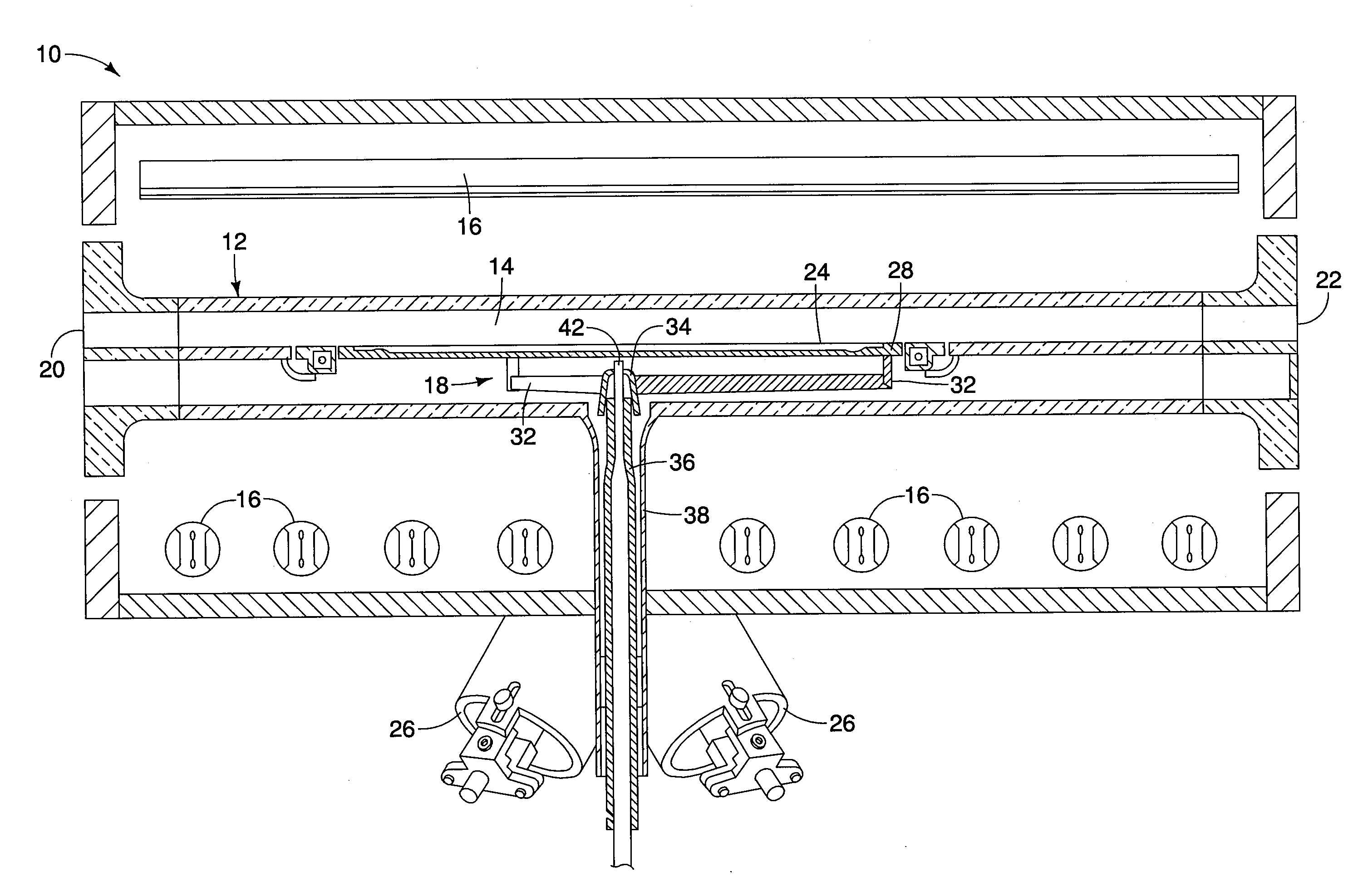
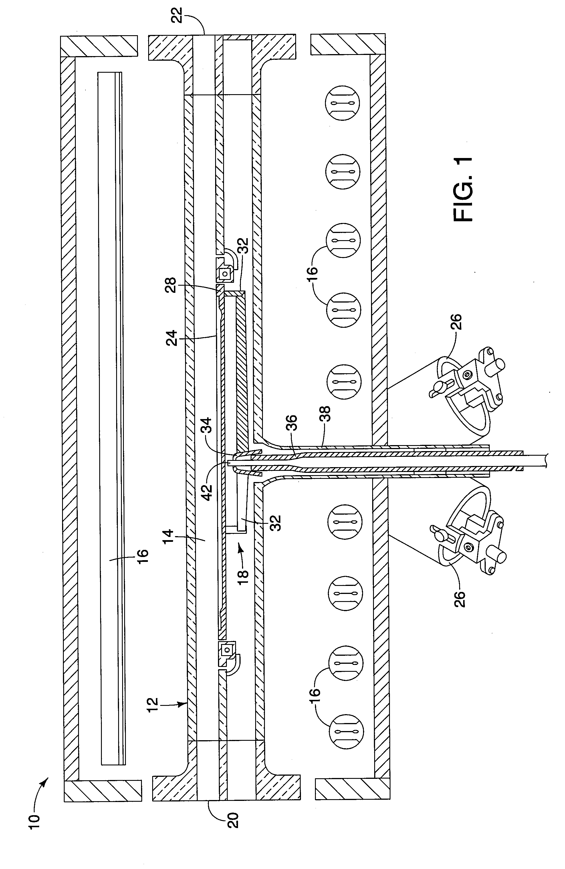
[0032]Referring to FIG. 1, an exemplary embodiment of a chemical vapor deposition (“CVD”) reactor 10 is shown. While the illustrated embodiment is a single substrate, horizontal flow, cold-wall reactor, it should be understood by one skilled in the art that the thermocouple technology described herein may be used in other types of semiconductor processing reactors as well as other applications requiring accurate temperature sensors. The reactor 10 includes a reaction chamber 12 defining a reaction space 14, heating elements 16 located on opposing sides of the reaction chamber 12, and a substrate support mechanism 18. The reaction chamber 12 is an elongated member having an inlet 20 for allowing reactant gases to flow into the reaction space 14 and an outlet 22 through which the reactant gases and process by-products exit the reaction space 14. In an embodiment, the reaction chamber 12 is formed of transparent quartz. It should be understood by one skilled in the art that the reactio...


PUM


Abstract

A thermocouple for measuring temperature at a position adjacent to a substrate being processed in a chemical vapor deposition reactor is provided. The thermocouple includes a sheath having a measuring tip. The thermocouple also includes a support tube disposed within the sheath. The thermocouple further includes first and second wires supported by the support tube. The first and second wires are formed of different metals. A junction is formed between the first and second wires, wherein the junction is located adjacent to a distal end of the support tube. A spring is disposed about a portion of the support tube. The spring is compressed to exert a spring force on the support tube to bias the junction against the measuring tip to maintain the junction in continuous contact with the measuring tip. The spring force is small enough to prevent significant deformation of the junction as well as reducing variation of spring force or junction location from one thermocouple to another.

Description

FIELD OF THE INVENTION[0001]The present invention relates to a temperature sensor, and more particularly to a temperature sensor configured to enhance accuracy of temperature control in a semiconductor processing apparatus.BACKGROUND OF THE INVENTION[0002]Semiconductor processing chambers are used for depositing various material layers onto a substrate surface or surfaces at low temperatures (less than 700° C.) or high temperatures (greater than 700° C.) and at atmospheric or reduced pressure within the processing chamber. One or more substrates, or workpieces, such as silicon wafers, are placed on a workpiece support within the processing chamber. Both the substrate and workpiece support are heated to a desired temperature. In a typical processing step, reactant gases are passed over the heated substrate, whereby a chemical vapor deposition (“CVD”) reaction deposits a thin layer of the reactant material onto the substrate surface(s). Through subsequent processes, these layers are m...

Claims


Application Information

Patent Timeline
IPC IPC(8): G01K7/02B05C11/00
CPCG05D23/2228G01K7/04G05D23/1931G05D23/22
Inventor HALPIN, MIKEGOODMAN, MATT
Owner ASM IP HLDG BV
Why Eureka
Try Eureka