Machine tool and method of controlling machine tool

a technology of machine tools and tools, applied in the direction of machine control, process and machine control, electric programme control, etc., can solve the problems of increasing the overall weight of the apparatus, increasing the processing time, and another obstacle to further improving space efficiency, etc., to achieve high space efficiency, compact structure, and high stability

Inactive Publication Date: 2009-02-26
HONDA MOTOR CO LTD
View PDF21 Cites 34 Cited by
  • Summary
  • Abstract
  • Description
  • Claims
  • Application Information

AI Technical Summary

Benefits of technology

[0043]The present invention has the object of providing a machine tool with a compact structure, with high space efficiency, yet which is lightweight and highly stable.

Problems solved by technology

Moreover, because a heavy slide member is moved, in order to obtain sufficient stability, a base portion must be provided and affixed, such that the overall weight of the apparatus becomes quite heavy.
Furthermore, due to the fact that a unit including a processing spindle slides horizontally in the X direction, a moment force is generated with respect to the floor, which tends to shake the equipment laterally about a support point.
Further, with the configuration of Patent Document 3, even if the machine width is made smaller, because the length of the rotation arm is not changed, in the case that a plurality of machine tools are arranged adjacent to one another, the machine tools must be positioned while being separated sufficiently so that the rotation arms thereof do not interfere mutually with each other, thus presenting another obstacle to further improving space efficiency.
Further, with the structure of Patent Document 3, even though the width of the machine tool and the installation area thereof may be small, transporting of workpieces between each of the machine tools is not automated, and moreover, even if such an automated system were provided, with a slow transport mechanism, the processing time becomes longer as a result, and efficiency is poor.
In addition, when the workpiece transport mechanism is provided separately from the mechanism that fixes the workpiece and processing is performed thereon, delivery of workpieces between both of these mechanisms is required, so that the mechanisms and processing sequence becomes complex.
Still further, with such a complicated mechanism, the overall scale is increased, so that the point of making the machine tool itself smaller in scale is overlooked.
However, when the occupied area by the machine tool is small, the space for storing such multiple tools vanishes as well.
When a mechanism is adopted as described above, in which the horizontal X-direction slide mechanism of the machine tool in Patent Document 3 is rotated by 90° so as to become vertically oriented, since the machine tool assumes a shape of being longer than it is wide, if a mechanism were added for storing tools, the slider is brought into an imbalance state and worsened by generation of vibrations and the like, and processing precision tends to be lowered.
Notwithstanding, because a large number of workpiece shapes exist as described above, a large number of pallets corresponding to the various shapes of the workpieces must be prepared, and thus the manufacturing cost for the table, as well as the storage location therefor, etc., tends to cause problems.
However, with the pin positioning device disclosed in the aforementioned Patent Document 5, because the workpiece, which is the object to be positioned, is a printed wiring board to be inspected, it cannot be assumed that a large load (e.g., a radial load or the like), such as the cutting resistance that is incurred during processing by a machine tool, would be imposed on the positioning pins and the moving elements therefor.
Furthermore, in the case of a machine tool that carries out machining on the aforementioned engine components, because machining chips (cutting chips) of the workpieces are generated, which could cause problems in the seals of the aforesaid moving elements, it would be difficult to divert use of the aforementioned positioning pin apparatus for the purpose of positioning workpieces for a machine tool.
Thus, manufacturing costs for the table, as well as the storage location therefor, etc., tends to cause problems.
However, with such a pin positioning device, because the workpiece, which is the object to be positioned, is a printed wiring board to be inspected, use thereof with a machine tool cannot be envisioned.
More specifically, a structure is provided for positioning the printed wiring board while the pins are moved and retained at predetermined positions, and thus, positioning of the workpiece is not carried out precisely, and automatization thereof is difficult.
Because a pallet supporting base and a table displacing mechanism, etc., are required, it is difficult for the table as well as other devices in the periphery around the table to be made small in scale.
Thus, the position of the reference hole of the workpiece, corresponding to the fixed pin on the workpiece positioning table according to the above conventional configuration, is not limited to a fixed position, and in particular, when processing is performed on the side surfaces of the workpiece, it would be difficult for the processing surface to face toward the front of the tool, and thus accurate and rapid processing is difficult to carry out.
Therefore, the structure of the table is complex and the weight thereof is large.

Method used


Image

  • Machine tool and method of controlling machine tool
  • Machine tool and method of controlling machine tool
  • Machine tool and method of controlling machine tool

Examples


first embodiment

[0193]In the first embodiment, because the disk 62 is constructed by the leaf spring, by gripping the disk 62, the rotation arm 32 can reliably be prevented from rotating without falling off.

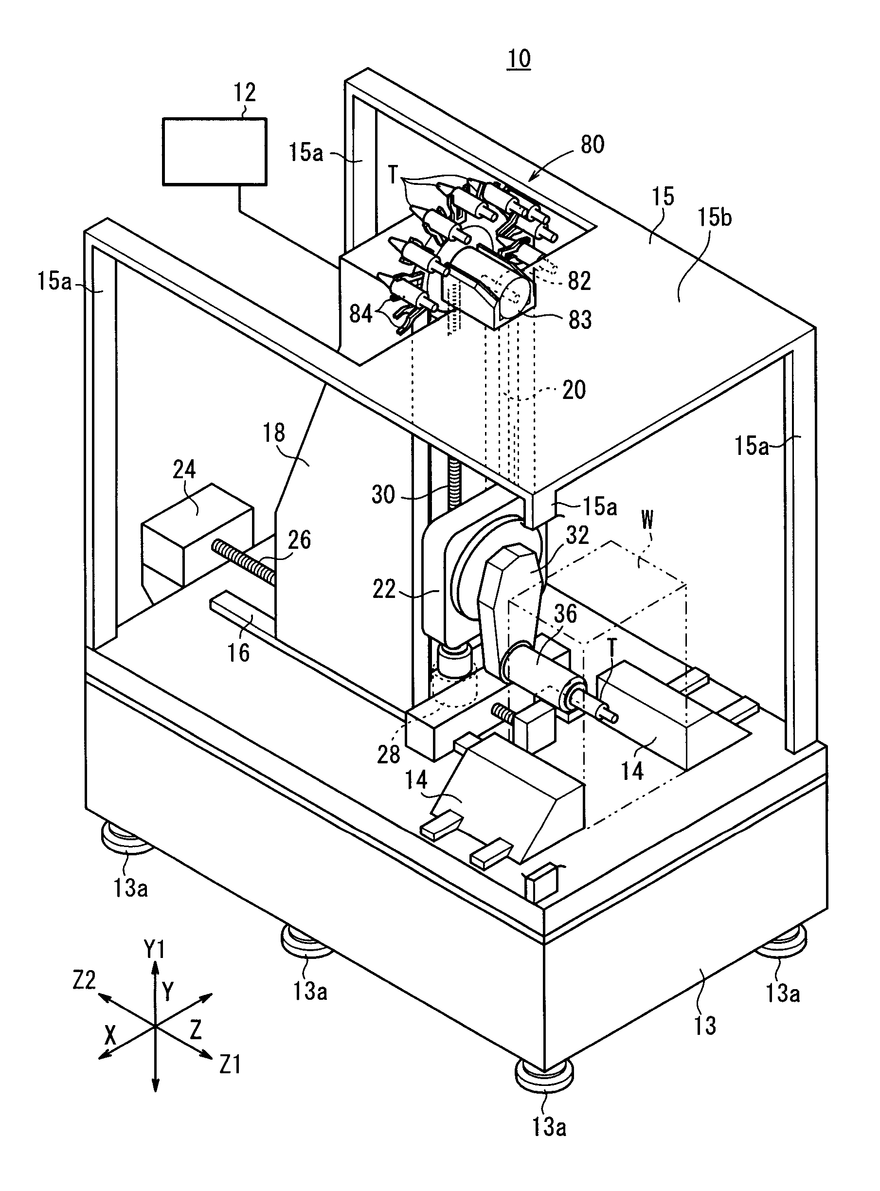
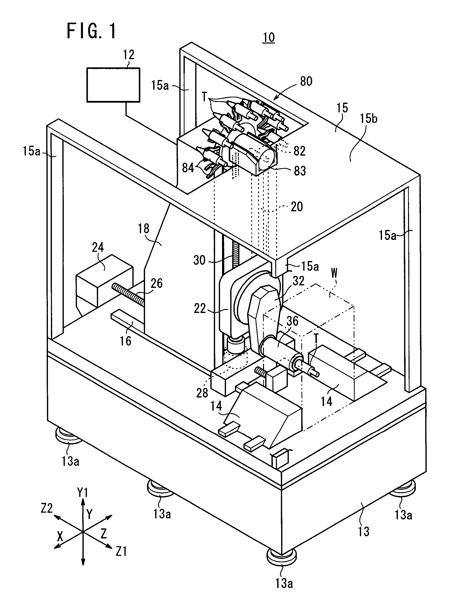
[0194]As shown in FIG. 5, on a surface on the side of the arrow Z1 on an upper portion of the column 18 on the machine tool 10, an unclamping block 78 is disposed for pressing the aforementioned unclamping lever 52. Accordingly, in a state in which the rotation arm 32 points upwardly, by raising the supporting body 22, the unclamping lever 52 is operated on by the unclamping block 78, whereby the tool T in the tool head 50 can be unclamped.

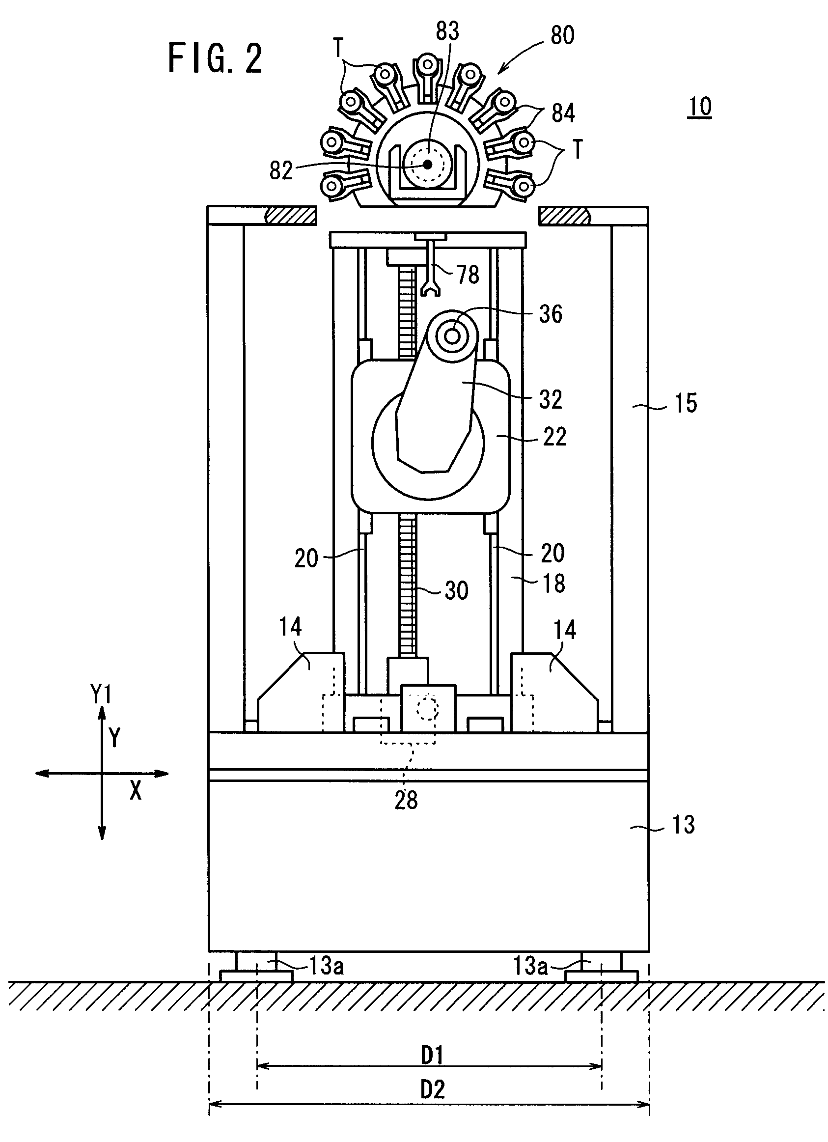
[0195]A rotating magazine 80 storing a plurality of tools T therein, which are capable of attachment and detachment on the processing spindle 36, is disposed on an upper surface of the plate 15b on the frame 15. The rotating magazine 80 includes an axis of rotation 82 that extends in the direction of the arrow Z, a magazine motor 83 for driving the axis of rot...

second embodiment

[0204]Further, in accordance with a machine tool 10 the components that move in the vertical plane are the supporting body 22, which moves slidably in the vertical direction, and the two axes of the rotation arm 32, and because there are no axes that move in a lateral direction, the machine tool 10 has a narrow and extremely compact structure, and space efficiency can be improved. Because the frontal width of the machine tool 10 is small, transportation of workpieces to other adjacent machine tools is facilitated, while operability of the machine tool 10 is enhanced.

[0205]Further, the supporting body 22 moves slidably in a vertical direction, and a moment that causes lateral shaking about the foundation is not generated. Furthermore, because the rotation arm 32 is lightweight, even when rotated, the stability thereof is not lost or adversely affected. Accordingly, the machine tool 10 can be constructed so as to be lightweight, yet high stability is obtained.

[0206]Because the machin...

third embodiment

[0358]FIG. 42 is a partial cutaway perspective view of a machine tool 4012 on which a workpiece positioning table 4010 is mounted FIG. 43 is a plan view of the machine tool 4012, and FIG. 44 is a front view of the machine tool 4012. The machine tool 4012 is a so-called numerically controlled machine tool (NC machine tool), which enables highly precise positioning of a tool T.

[0359]The machine tool 4012 comprises a base 4014, with a table 4010 serving as a workpiece positioning table, a spindle head unit 4018, which axially supports a spindle unit 4016 rotationally, and in addition, so as to be movable to a given position in three dimensions, consisting of two horizontal directions (the arrow Z-axis direction, and the arrow X-axis direction perpendicular to the Z-axis direction) and a vertical direction (the arrow Y-axis direction), and a tool exchanging unit 4020. A workpiece W (see FIG. 45), which is processed by the machine tool 4012, is positioned on and affixed to the table 401...


PUM

PropertyMeasurementUnit
angleaaaaaaaaaa
angleaaaaaaaaaa
angleaaaaaaaaaa

Abstract

A machine tool (10) has a Z table (18) sliding in the Z direction in a horizontal plane, a support body (22) provided on the Z table (18) and sliding in the vertical direction, a rotation arm (32) supported at the support body (22) and endlessly rotatable in a vertical plane facing work (W), an arm motor (34) for rotating the rotation arm (32), a processing spindle (36) rotatably supported and placed at a position of a distance R from the center C of rotation of the rotation arm (32), and a spindle motor (38) for rotating the processing spindle (36).

Description

TECHNICAL FIELD[0001]The present invention relates to a machine tool equipped with a plurality of machine tools having a rotation arm, which is rotatable in a vertical plane, and a processing spindle directed horizontally in the vicinity of the rotation arm, along with a method of controlling a machine tool on which a stocker, which retains a plurality of required tools therein for processing a workpiece, is disposed.[0002]Further, the present invention concerns a workpiece positioning table that is utilized by a machine tool for manufacturing various types of components, and a machine tool equipped with such a table.BACKGROUND ART[0003]From the viewpoints of improving installation space efficiency, transporting workpieces to adjacent machine tools, and operability of an operator, in a machine tool, it is preferable for the occupied area to be small, and in particular, it is desirable for the width as viewed from the front to be small. For the purpose of making the occupied area sma...

Claims


Application Information

Patent Timeline
Patent Type & Authority Applications(United States)
IPC IPC(8): B23C1/14G06F19/00G05B19/19G05B19/4065
CPCB23Q1/623Y10T483/136B23Q39/04B23Q2230/002Y10T29/5196Y10T483/1752Y10T409/309576Y10T409/307168Y10T409/307616Y10T483/10Y10T409/307952Y10T409/308232Y10T409/309016Y10T409/305656Y10T409/305432Y10T409/307784Y10T483/1795Y10T483/175Y10T483/1855Y10T29/5155Y10T409/309352B23Q3/15706B23Q1/28B23Q1/54B23Q1/70
Inventor YAMAURA, YUKIKOIZUMI, TATSUYANAKAMURA, TAROINAKI, KATSUMUNEUCHIKAWA, MOTOKITANIZAKI, KOUICHIARAKAWA, SHUGOTANAKA, TATSUHIKOMIYAGI, TOMOYOSHIMOTOJIMA, TAKAYUKI
Owner HONDA MOTOR CO LTD
Why Eureka
Try Eureka