Supercharge Your Innovation With Domain-Expert AI Agents!

Apparatus and method for reducing eccentricity and out-of-roundness in turbines

a turbine and eccentricity technology, applied in mechanical apparatus, machines/engines, liquid fuel engines, etc., can solve the problems of large non-standard casing surface non-uniformity, high differential pressure drop across the hole, and inability to achieve uniform heat transfer coefficient, etc., to achieve a high degree of control over the flow

Active Publication Date: 2009-02-26
GENERAL ELECTRIC CO
View PDF5 Cites 27 Cited by
  • Summary
  • Abstract
  • Description
  • Claims
  • Application Information

AI Technical Summary

Benefits of technology

[0012]In a further embodiment, a method for controlling clearance between tips of turbine blades and a casing of a gas turbine, is disclosed and includes: receiving clearance information; determining an amount of cooling air to be supplied to sections of the casing; and regulating flow from a source of cooling air to each section of the casing to reduce the clearance.

Problems solved by technology

One problem for air impingement cooling systems on gas turbines is the ability to achieve a uniform heat transfer coefficient across large non-uniform non-standard casing surfaces.
One detrimental impact of applying small impingement cooling holes is the need for operating with high differential pressure drop across the holes.
This results in the requirement for undesirable high cooling air supply pressures which negatively impacts net efficiency.
However, the impingement systems used on aircraft engines cannot be used in some turbine applications.
It is not feasible to use compressor extraction air on some other gas turbines because the design heat transfer coefficients require cooler air temperatures.
For example, some other gas turbines have a significantly larger, non-uniform casing surface that requires an intricate manifold design as compared to aircraft engines.
A problem with eccentricity and out-of-roundness for the gas turbine casing is rub between the rotor and the stator and other mechanical problems.
This decreases efficiency of the power output.
The problem is primarily addressed by increasing the cold built clearance of the gas turbines, which does not address the problem, but further lowers the efficiency.

Method used


Image

  • Apparatus and method for reducing eccentricity and out-of-roundness in turbines
  • Apparatus and method for reducing eccentricity and out-of-roundness in turbines
  • Apparatus and method for reducing eccentricity and out-of-roundness in turbines

Examples


Embodiment Construction

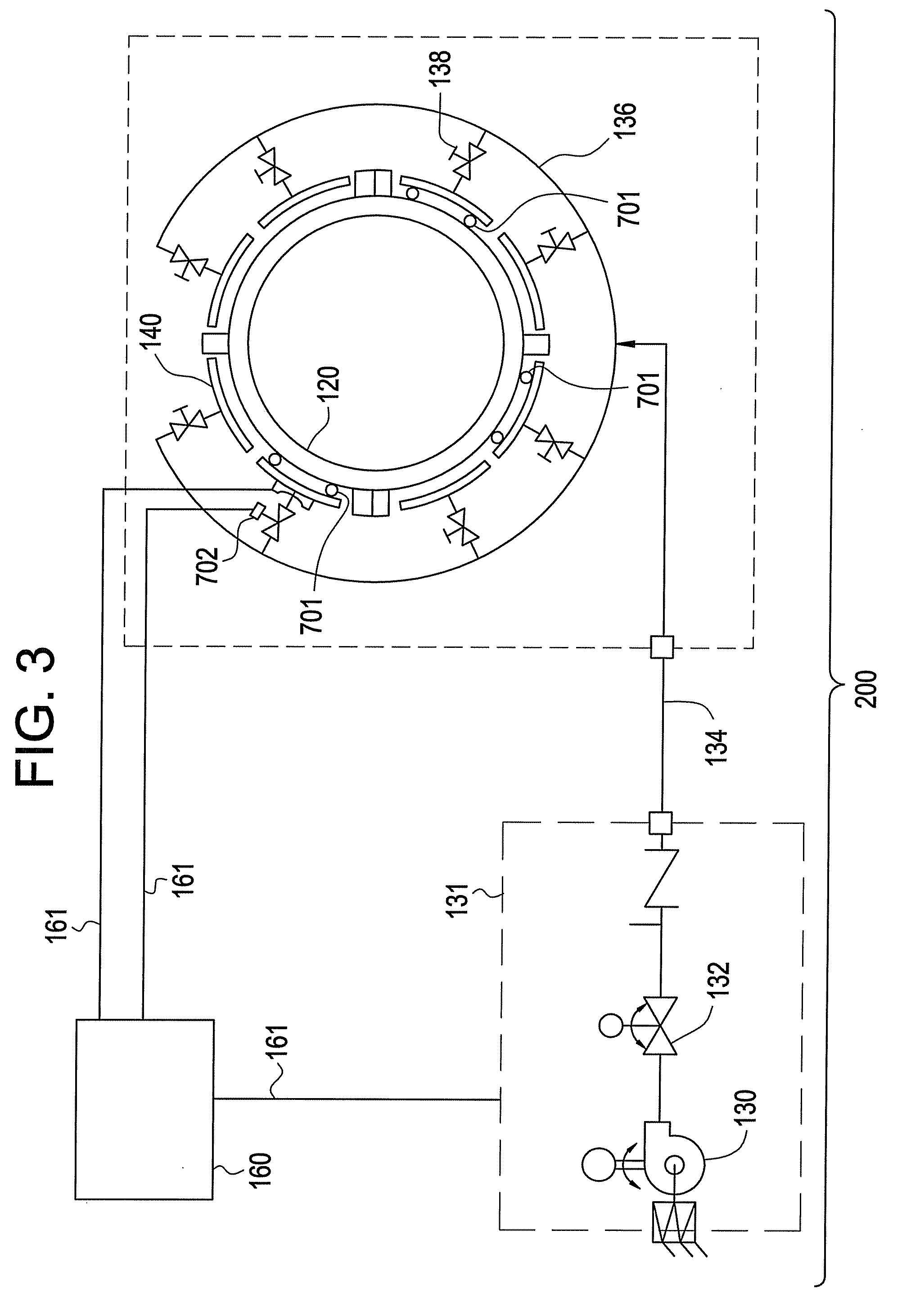
[0021]Disclosed are methods and apparatus for active clearance control using cooling manifolds in a gas turbine engine. The cooling flow of each individual manifold is regulated by devices such as tuning valves or orifices. Clearance control makes use of information of overall eccentricity and out-of-roundness and local clearance in sectors. The information may be collected in a variety of ways, including with the use of clearance probes. Prior to discussing the methods and apparatus in greater detail, certain aspects of a gas turbine are discussed for perspective.

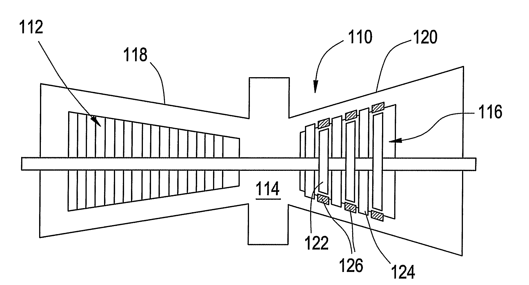
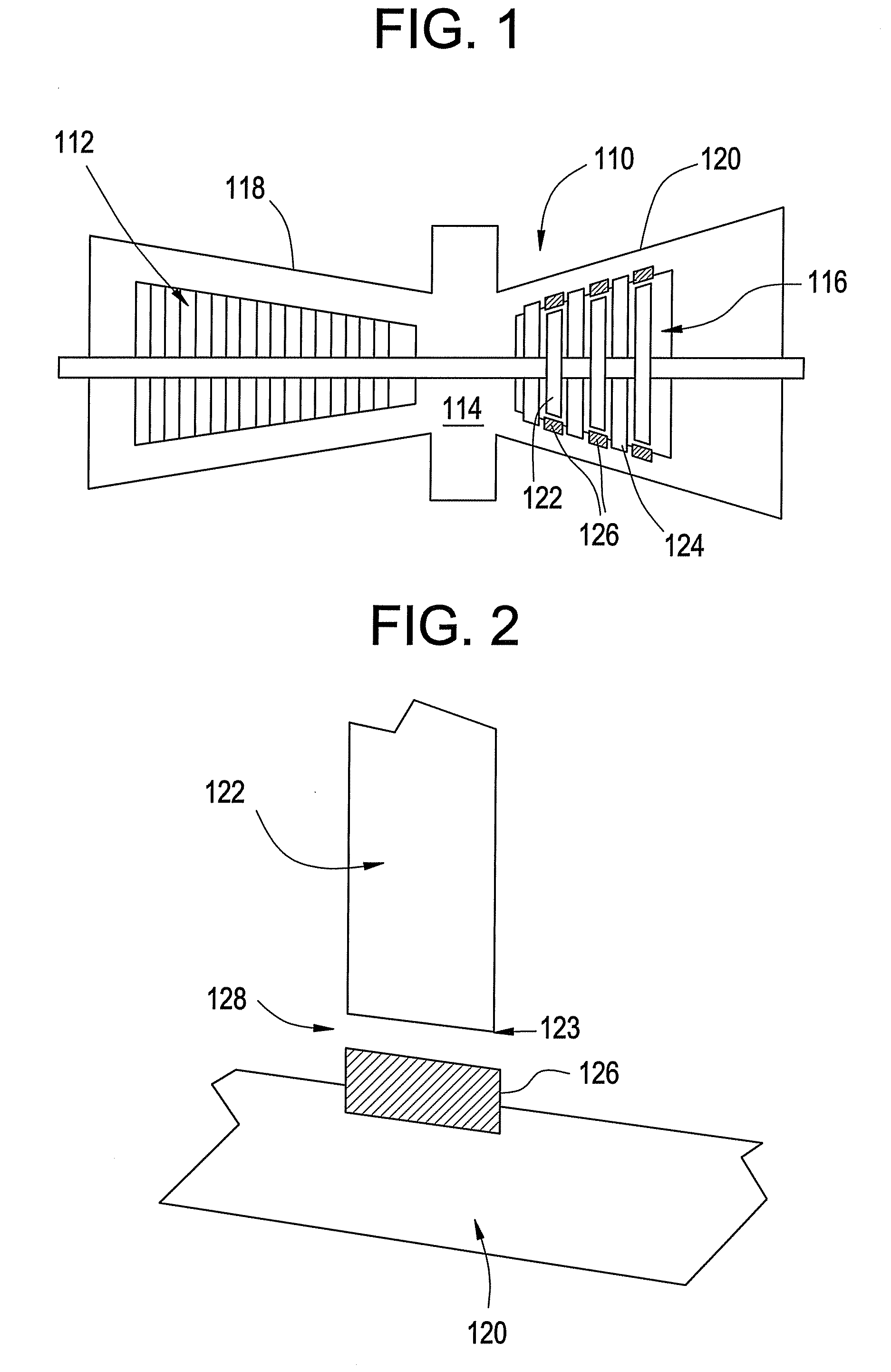
[0022]Turning now to FIG. 1, there is illustrated therein an exemplary embodiment of a gas turbine 110. The gas turbine 110 includes a compressor section 112, a combustor section 114 and a turbine section 116. The gas turbine 110 also includes a compressor casing 118 and a turbine casing 120. The turbine casing 118 and the compressor casing 120 enclose major parts of the gas turbine 110. The turbine section 116 includes a ...


PUM


Abstract

A turbine includes: a plurality of turbine blades arranged within a casing, the arrangement including a clearance between tips of the blades and the casing; a plurality of manifolds disposed proximate to the casing opposite the clearance, wherein each of the manifolds includes a plurality of impingement holes in the surface thereof; a source of clearance information; and a source of cooling air for supplying cooling air through a plurality of flow control devices to selected ones of the manifolds according to the clearance information. A system and a method are also provided.

Description

CROSS REFERENCE TO RELATED APPLICATION[0001]The subject matter disclosed herein is generally related to U.S. patent application Ser. No. 11 / 548,791, entitled “Turbine Case Impingement Cooling for Heavy Duty Gas Turbines,” filed Oct. 12, 2006.BACKGROUND OF THE INVENTION[0002]1. Field of the Invention[0003]The teachings herein relate to reducing eccentricity and out-of-roundness in a turbine, and, in particular, to techniques for controlling cooling.[0004]2. Description of the Related Art[0005]Air impingement cooling has been used to manage the casing temperature of small gas turbines and to reduce and maintain the clearances between rotating blades and accompanying interior casing surfaces. One problem for air impingement cooling systems on gas turbines is the ability to achieve a uniform heat transfer coefficient across large non-uniform non-standard casing surfaces. On small gas turbines, small impingement holes and short nozzle to surface distances are normally applied. These fact...

Claims


Application Information

Patent Timeline
Patent Type & Authority Applications(United States)
IPC IPC(8): F01B25/04
CPCF01D11/24F05D2260/201Y02T50/676Y02T50/60
Inventor ZHANG, HUAWHALING, KENNETH NEILSEALE, JASON ALLENERICKSON, DEAN MATTHEWMICHALSKI, MICHAEL FRANCIS
Owner GENERAL ELECTRIC CO
Features
  • R&D
  • Intellectual Property
  • Life Sciences
  • Materials
  • Tech Scout
  • Unparalleled Data Quality
  • Higher Quality Content
  • 60% Fewer Hallucinations
Learn More