Condensate Pump

Inactive Publication Date: 2009-02-26
DIVERSITECH
View PDF37 Cites 9 Cited by
  • Summary
  • Abstract
  • Description
  • Claims
  • Application Information

AI Technical Summary

Benefits of technology

[0005]The present invention addresses the issues raised by the installation of a condensate pump in an extreme environment. Particularly, the condensate pump of the present invention is capable of operating reliably in such an extreme environment over an extended period of time. Further, the condensate pump of the present invention is designed to operate quietly and efficiently.
[0008]Quiet operation is also enhanced by the design of the cylindrical volute chamber of the impeller pump. Particularly, the transition from the cylindrical volute chamber to the tangential output port of the impeller pump has a swept diagonal surface that creates a gradual transition from the cylindrical volute chamber to the tangential output port. The gradual transition minimizes the pulsing that occurs each time the water between successive blades of the impeller rushes through the output port of the volute chamber. The reduction of pulsing by the smooth transition to the tangential output port increases efficiency and reduces noise of the impeller pump.

Problems solved by technology

Condensate pumps are often located in extreme environments and are subjected to moisture, heat, and cold.
Moreover, condensate pumps are often installed in inaccessible locations where maintenance is difficult, and therefore reliability over many years is necessary.

Method used


Image

  • Condensate Pump
  • Condensate Pump
  • Condensate Pump

Examples


Embodiment Construction

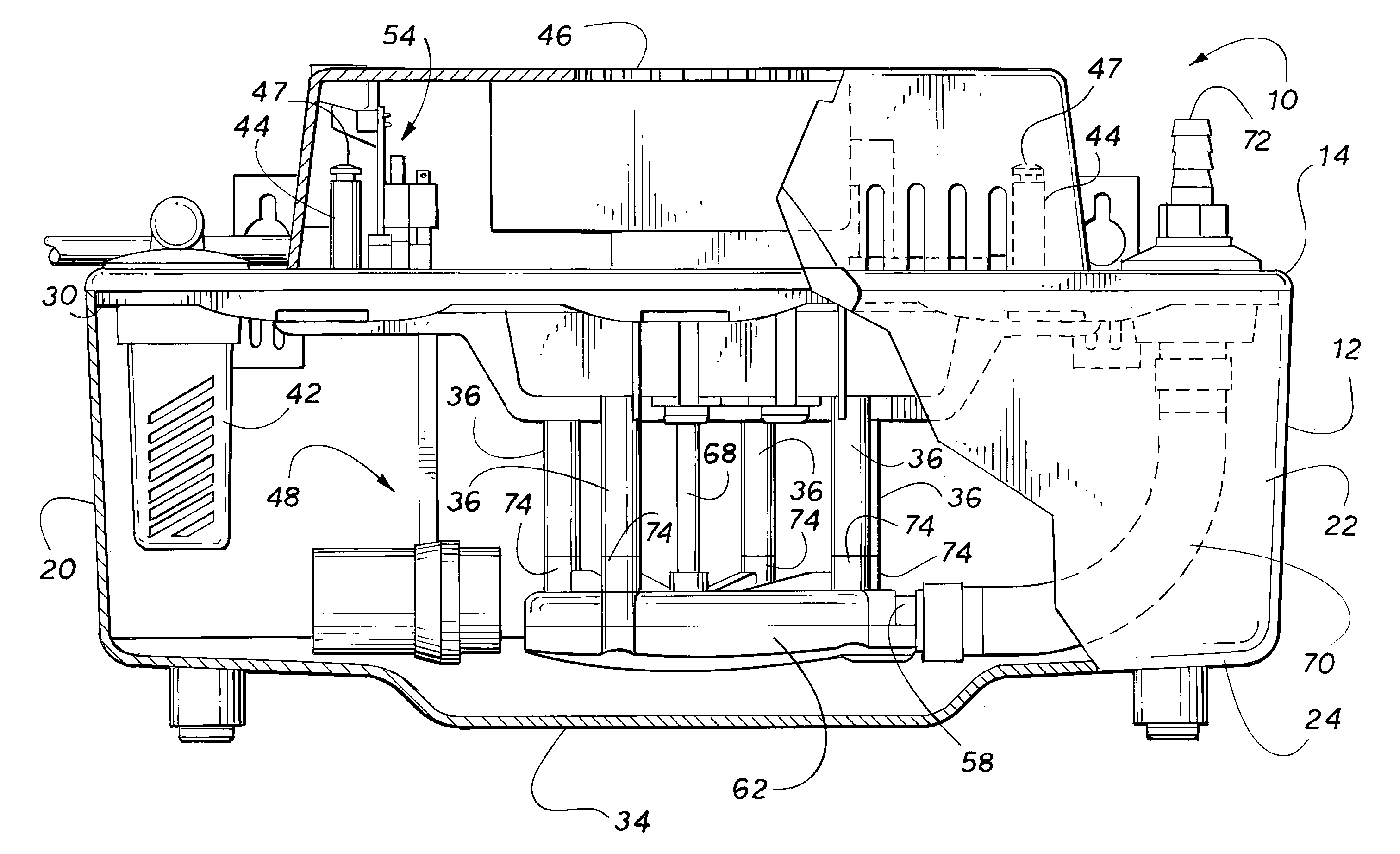
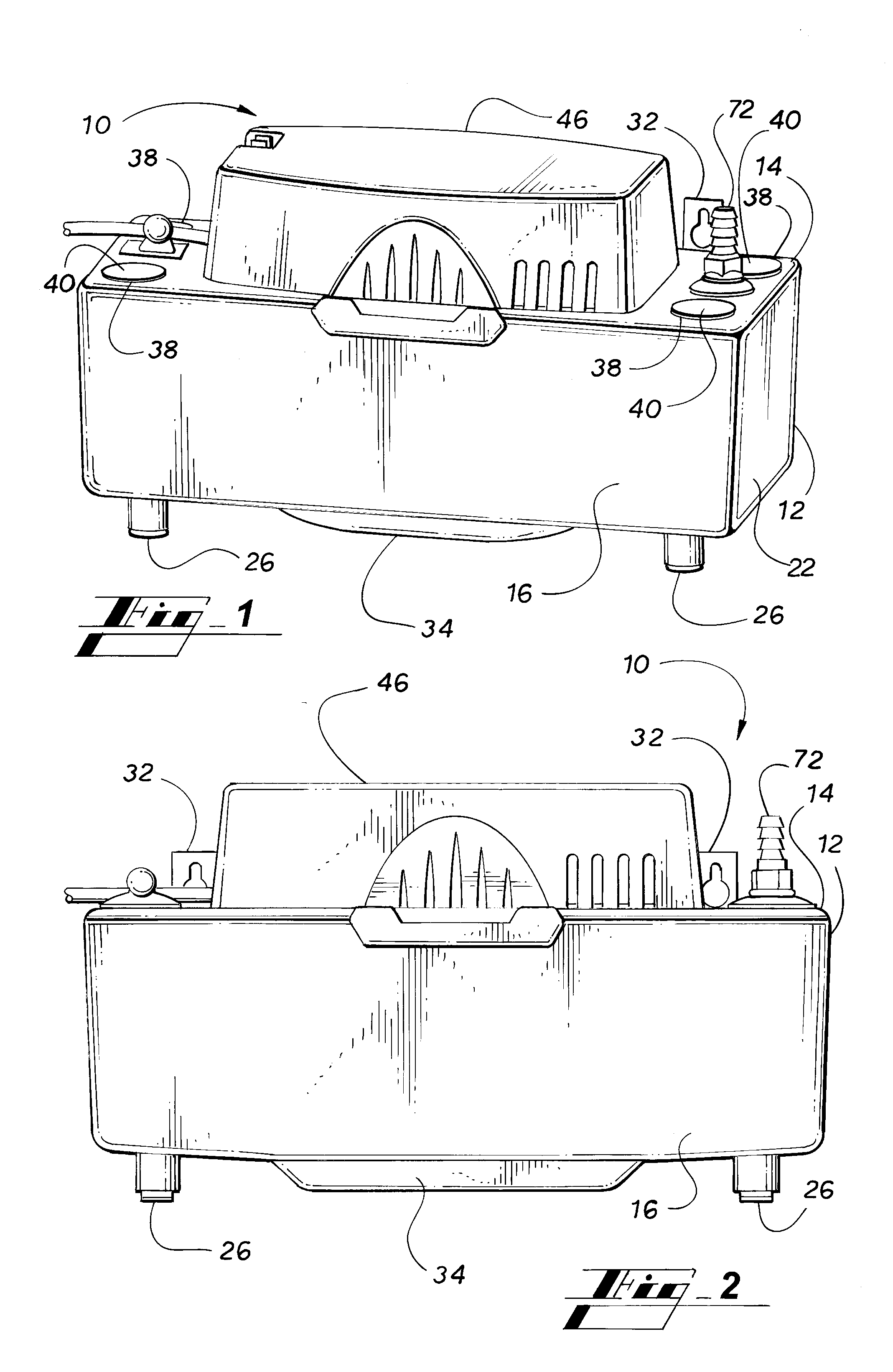
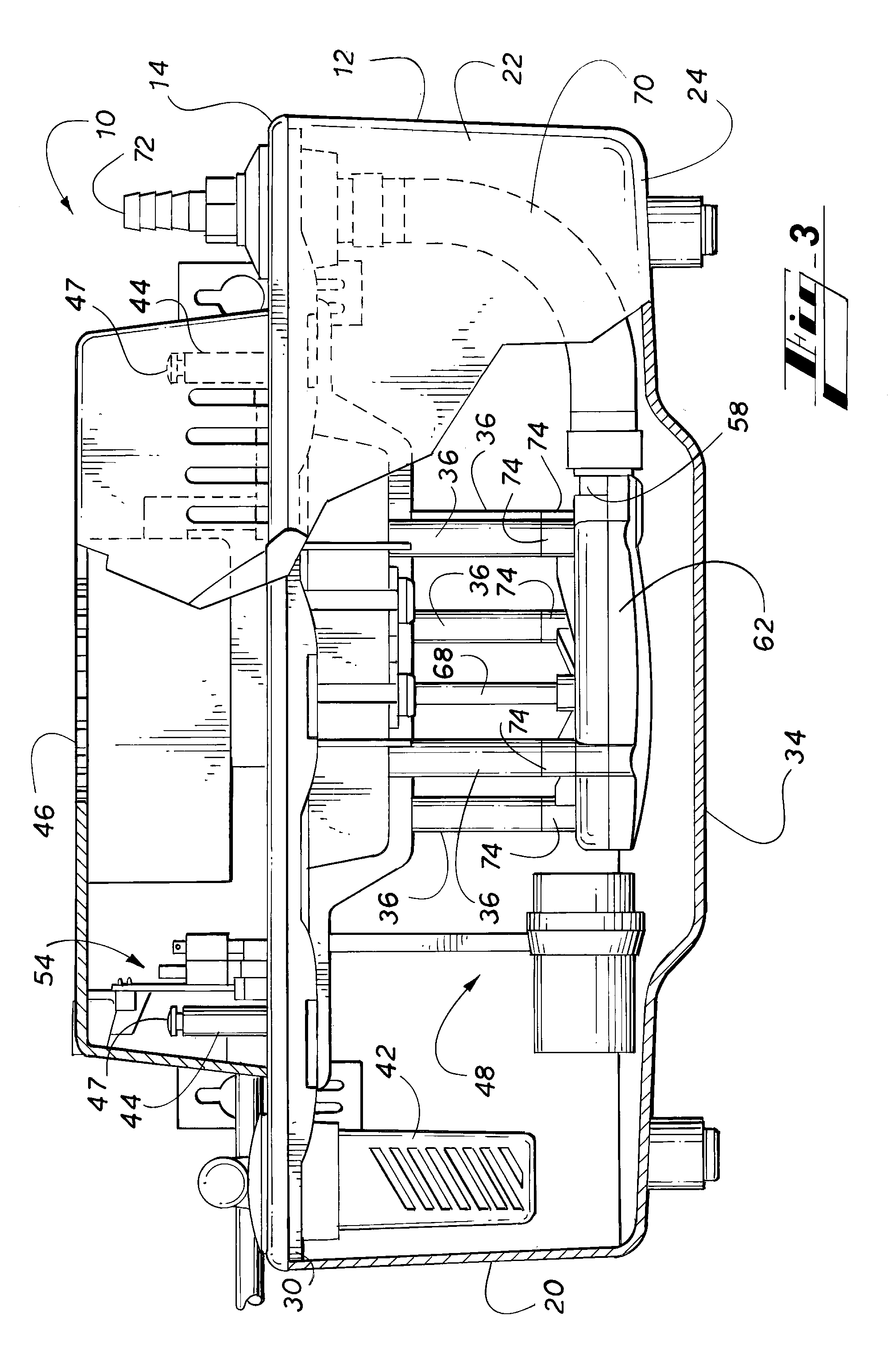
[0035]Turning to FIG. 1-8 and 11, a condensate pump 10 in accordance with the present invention comprises a reservoir 12 and a unitary top support plate 14. The reservoir 12 comprises a water tight container with an open top defined by a periphery 28 (FIG. 11). In one embodiment the reservoir comprises a front panel 16, a back panel 18, a left side panel 20, a right side panel 22, and a bottom panel 24. The reservoir may be of any geometric shape. The reservoir 12 has rubber support legs 26 located on the four corners of the bottom panel 24. The unitary top support plate 14 has a flange 30 (FIGS. 4, 6, 8, and 11) around its periphery which engages the periphery 28 of the reservoir 12. In addition, hanger brackets 32 are mounted to the reservoir on the back panel 18. The hanger brackets 32 are used to mount the reservoir 12, on a wall or other elevated support in order to make later access to the condensate pump 10 in some cases easier. The reservoir 12 further has a trough 34 molded...


PUM


Abstract

A condensate pump for an HVAC system includes a reservoir, a unitary top support plate, and a cover. A pump motor, an impeller pump, a float, and control electronics are mounted on the unitary top support plate. The transition from the cylindrical volute chamber to the tangential output port of the impeller pump has a swept diagonal surface that creates a gradual transition from the cylindrical volute chamber to the tangential output port. The gradual transition minimizes the pulsing. An intake profile with a concave surface extends from the center of the impeller and matches a complementary intake profile extending from the bottom of the reservoir. Vortex inhibiting vanes are molded into the bottom of the reservoir adjacent the central intake port of the impeller pump to break up any induced vortex within the reservoir.

Description

CLAIM OF PRIORITY[0001]This application claims priority from U.S. Provisional Patent Application Ser. No. 60 / 956,741 filed on Aug. 20, 2007, which is incorporated herein in its entirety.FIELD OF THE INVENTION[0002]This invention relates to a condensate pump that collects condensate water from the evaporator of an HVAC system and pumps the condensate water to another location for disposal. More specifically, the condensate pump of the present invention includes an improved impeller pump, an improved component mounting assembly, and an improved reservoir attachment mechanism.BACKGROUND OF THE INVENTION[0003]A condensate pump is used in an HVAC system to collect condensate water from the evaporator of the HVAC system and to pump the condensate water to a remote location for disposal. Particularly, the condensate pump typically comprises a reservoir, an impeller pump for pumping the water out of the reservoir to the remote location, and an electric motor to drive the impeller pump. A fl...

Claims


Application Information

Patent Timeline
IPC IPC(8): F04B49/04F04D15/00
CPCF04D15/0218F04D29/426F04D29/448F04D29/708F24F13/222F04D29/4273F05D2250/52F04D29/445F05D2250/51
Inventor WARD, CHARLES BARRYBERTOLI, KENNETH
Owner DIVERSITECH
Why Eureka
Try Eureka