
Bipolar battery including a pressure sensor

a battery and pressure sensor technology, applied in the field of bipolar batteries, can solve the problems of high corrosion inside the battery, high cost of sensors that will endure the environment, and sensors that cannot adapt to the environment, so as to reduce the influence of the mechanism on the precise pressure, reduce the spring constant, and tighten the effect of elastic properties

Inactive Publication Date: 2009-02-26
NILAR INT AB
View PDF11 Cites 54 Cited by
  • Summary
  • Abstract
  • Description
  • Claims
  • Application Information

AI Technical Summary

Benefits of technology

[0015]In a preferred embodiment it may be desirable to deliberately make the part of the mechanism that comprises the gas envelope of the battery (such as a bellows, bladder, or balloon) much more mechanically compliant, i.e. with a much lower spring constant, to reduce the influence of the mechanism on the precise pressure at which the switching takes place. The material for the bellows, bladder, or balloon may be optimized for properties like hydrophobicity and sealing, and not have to have tight tolerances on its elastic properties.
[0016]An advantage with the bipolar battery according to the invention is that it is very inexpensive to implement, especially since a common gas space is used for all cells within the battery.
[0017]Another advantage with the bipolar battery according to the invention is that a more controlled charging procedure may be used that prevents the housing of the battery from breaking due to excessive internal pressure.

Problems solved by technology

The problem with monitoring the internal pressure is that a pressure sensor must be present in each cell, unless a common pressure chamber is used within the battery, to monitor the amount of pressure inside all the battery cells.
The environment inside the battery is highly corrosive, e.g. containing potassium hydroxide, and sensors not adapted to this environment will break down.
On the other hand sensors that will endure the environment are extremely expensive.
Furthermore, the device includes a disk spring which deforms and activates the safety device when a pressure on the membrane is too high.
There is no possibility to reset the apparatus to reuse the battery without replacing the diaphragm.
A drawback with the prior art pressure sensor is that it is provided in each battery cell which makes it expensive to implement.

Method used


Image

  • Bipolar battery including a pressure sensor
  • Bipolar battery including a pressure sensor
  • Bipolar battery including a pressure sensor

Examples


third embodiment

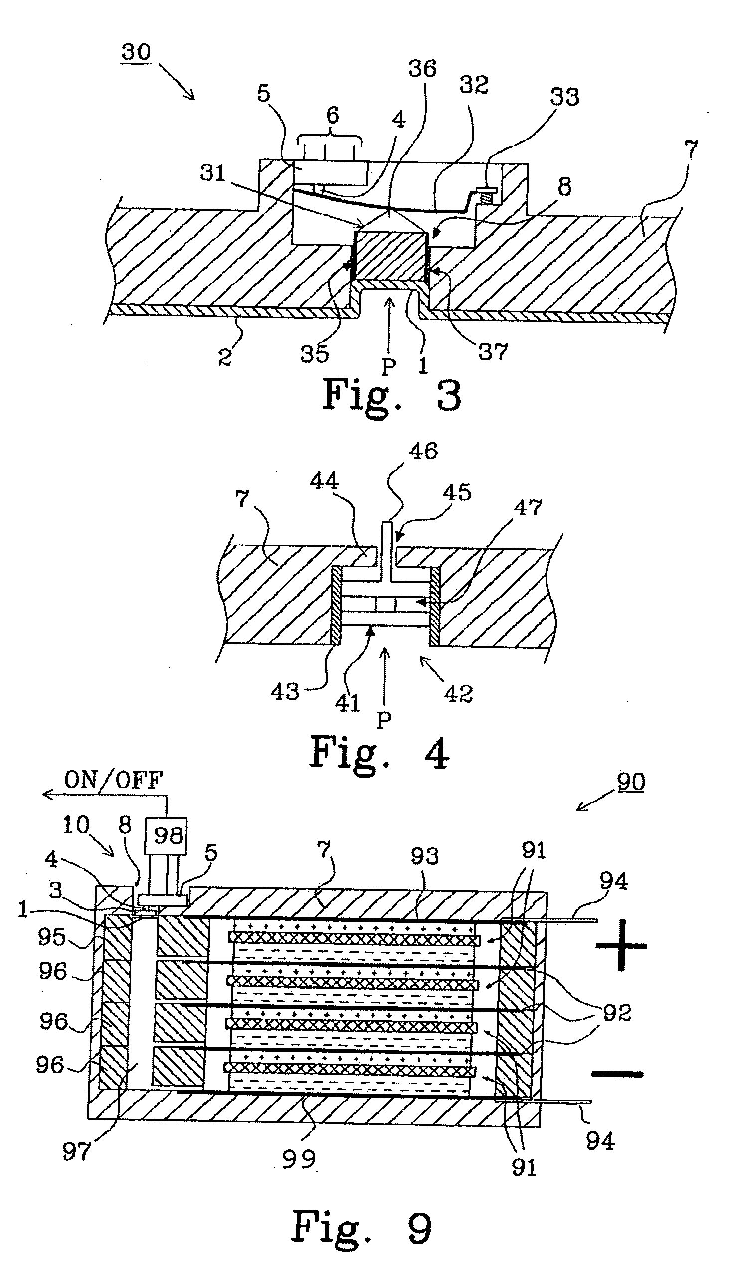
[0035]FIG. 3 shows a pressure sensor 30 provided with an adjustable spring arrangement. A pressure P from inside the battery cell is transformed into a reciprocal movement of the membrane 1, being a part of the hydrophobic barrier 2, as described in connection with FIG. 1. The membrane 1 acts as a balloon when the pressure P is applied from the inside due to the elasticity of the membrane 1. A moving item 31, hereafter called actuator, is placed inside the opening 8 of the housing 7, and on top of the membrane 1 opposite to the corrosive side of the membrane 1.

[0036]The adjustable spring arrangement, which is a pressure control means, comprises a spring 32 and a setting screw 33. The actuator 31 will affect the spring 32, and the spring constant can be set by adjusting a setting screw 33. The spring 32 is supported by the housing 7. A pressure increase will then affect the shape of the spring 32, that eventually will affect the contact 4 on the switch 5 and either short circuit the ...

fourth embodiment

[0041]FIG. 5 shows a pressure sensor 50 comprising a lever mechanism to make it more sensitive for a change in internal pressure P. A membrane 1 in the shape of a sealed bellow, said membrane being a part of the hydrophobic barrier 2, is provided into an opening 8. An actuator 48 is provided between the membrane 1 and the spring 32. A lever mechanism in the shape of a lever 51 with a protrusion 52 is provided, said protrusion being in contact with said spring and one end of the lever 51 being supported by the housing 7. The contact 4 of the switch 5 is in contact with a second end of the lever 51.

fifth embodiment

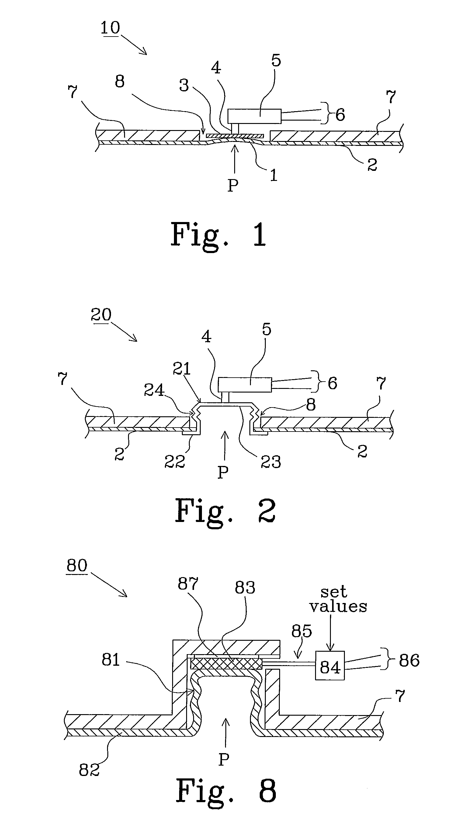
[0042]FIG. 8 shows a pressure sensor 80 comprising a bellows, bladder, or balloon structure, 81 formed in a gas tight outer seal 82, such as a membrane made from a hydrophobic barrier. A strain gauge 83, such as a piezo resistive MPX pressure sensor silicon device available from Freescale Semiconductor, is provided on top of, and in contact with, the bellows 81. Wires 85 are provided from the strain gauge through a casing, wherein the strain gauge 83 is pressed against the casing 7 when an internal pressure P increases. The stress / strain characteristics of the material of the strain gauge is known and well defined from the manufacturer, and an analogue signal is available at the wires 6 that indicate the amount of contact pressure on the strain gauge 83. Preferably, the bellows 81 in the membrane 82 has a much smaller spring constant and larger mechanical compliance than the material in the strain gauge 83, so dependence of the strain gauge signal on the bellows 81 is reduced to be ...


PUM


Abstract

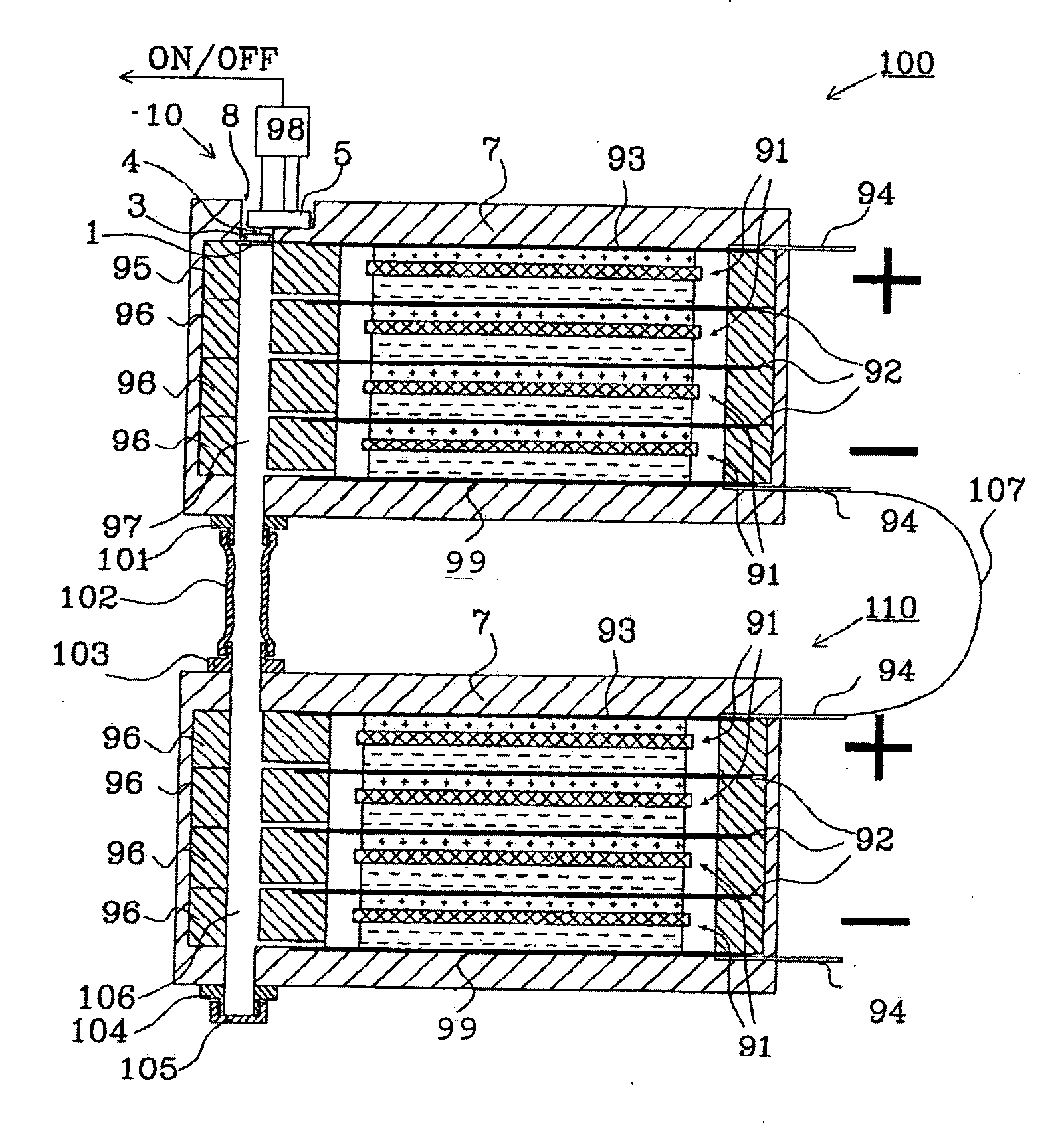
The present invention relates to a bipolar battery provided with a pressure sensor. The battery is provided with a housing 7 containing common gas space 97. The pressure sensor 10; 20; 50; 63; 80; 111 comprises: an actuator 3, 21; 31; 41; 48; 81 configured to transfer an internal pressure P within the common gas space to a reciprocal movement, and a switching device 5; 83 configured to generate a control signal indicative of changes in relation to an initial switching state generated by said reciprocal movement when the internal pressure exceeds a predetermined upper level. The pressure sensor further comprises a reset means 4; 32; 81 to automatically reset the switching device to the initial switch state when the internal pressure goes below a predetermined lower level, whereby said control signal is based on the internal pressure (P) within said sealed common gas space. The present invention also relates to a method for charging bipolar batteries.

Description

TECHNICAL FIELD[0001]The present invention relates to a bipolar battery having a common pressure chamber including a pressure sensor. The invention also relates to a method for charging a plurality of bipolar batteries having a pressure sensor.BACKGROUND TO THE INVENTION[0002]During charging of a battery, e.g. a bipolar battery, the temperature will increase due to the chemical reaction that occurs and the pressure inside each cell will also increase due to internal gassing caused by the chemical reaction. One way of controlling the charging of the battery is to monitor the temperature and adapting the amount of energy put into the battery in response to the temperature variations, but it is more advantageous to use the internal pressure to control the charging characteristics since the pressure is a better indicator of the chemical reaction that takes place inside the battery.[0003]The problem with monitoring the internal pressure is that a pressure sensor must be present in each c...

Claims


Application Information

Patent Timeline
IPC IPC(8): H01M2/12H01M2/18H01M10/04H01M10/48H01M50/184
CPCH01M2/08H01M2/1229H01M2200/20H01M10/0418H01M10/482H01M2/18Y02E60/10H01M50/325Y02P70/50H01M50/184
Inventor FREDRIKSSON, LARSHOWLETT, RICHARD
Owner NILAR INT AB
Learn More