
Apparatus and Method for Adaptive Polar Transmitter Linearization and Wireless Transmitter Employing the Same

a technology of adaptive polar transmitter and linearization method, which is applied in the field of wireless transmitters, can solve the problems of large and expensive, low signal quality, and large distortion of the signal, and achieves the effects of reducing distortion, reducing power consumption, and reducing signal distortion

Active Publication Date: 2009-02-26
TEXAS INSTR INC
View PDF3 Cites 22 Cited by
  • Summary
  • Abstract
  • Description
  • Claims
  • Application Information

AI Technical Summary

Benefits of technology

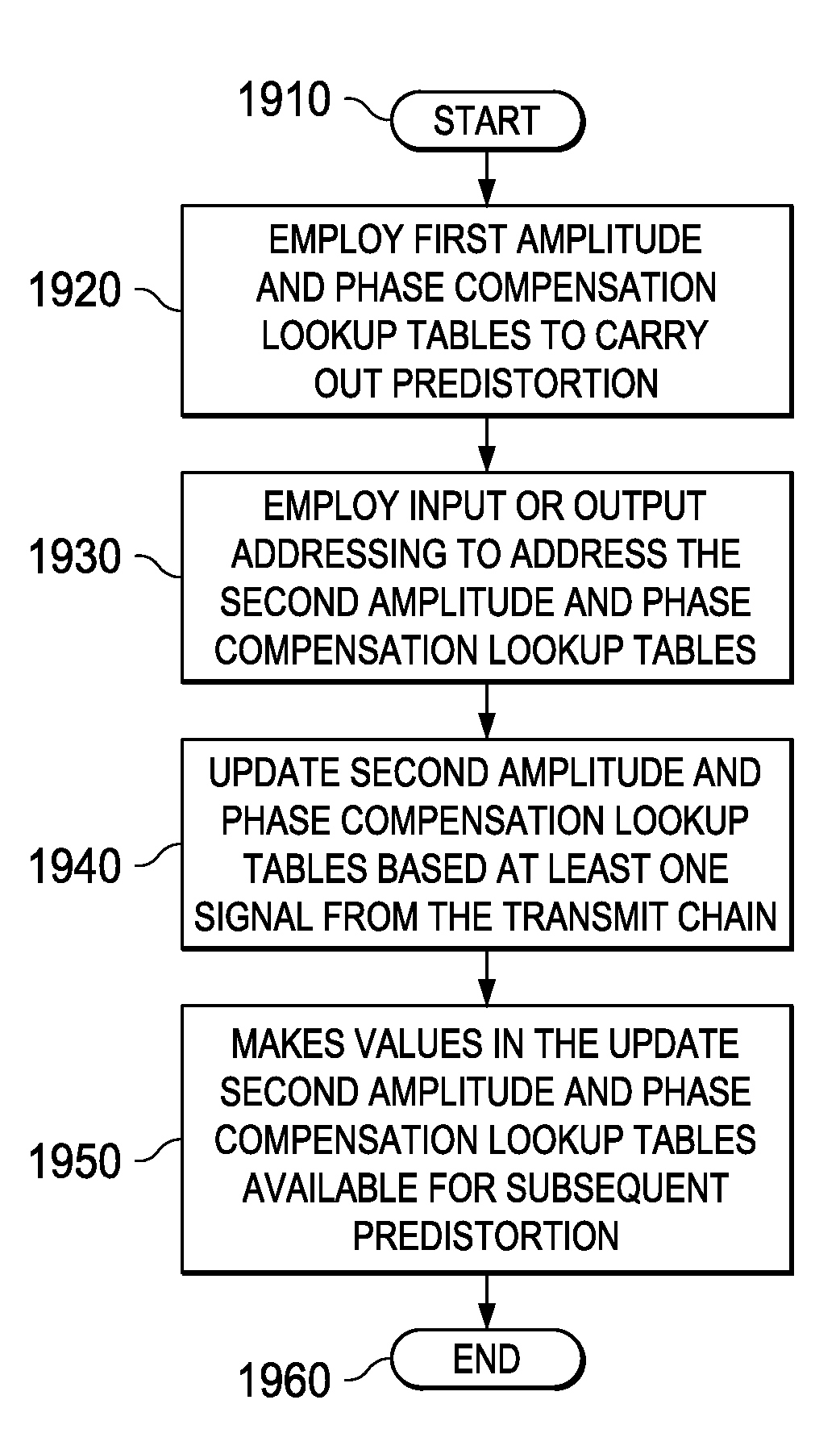
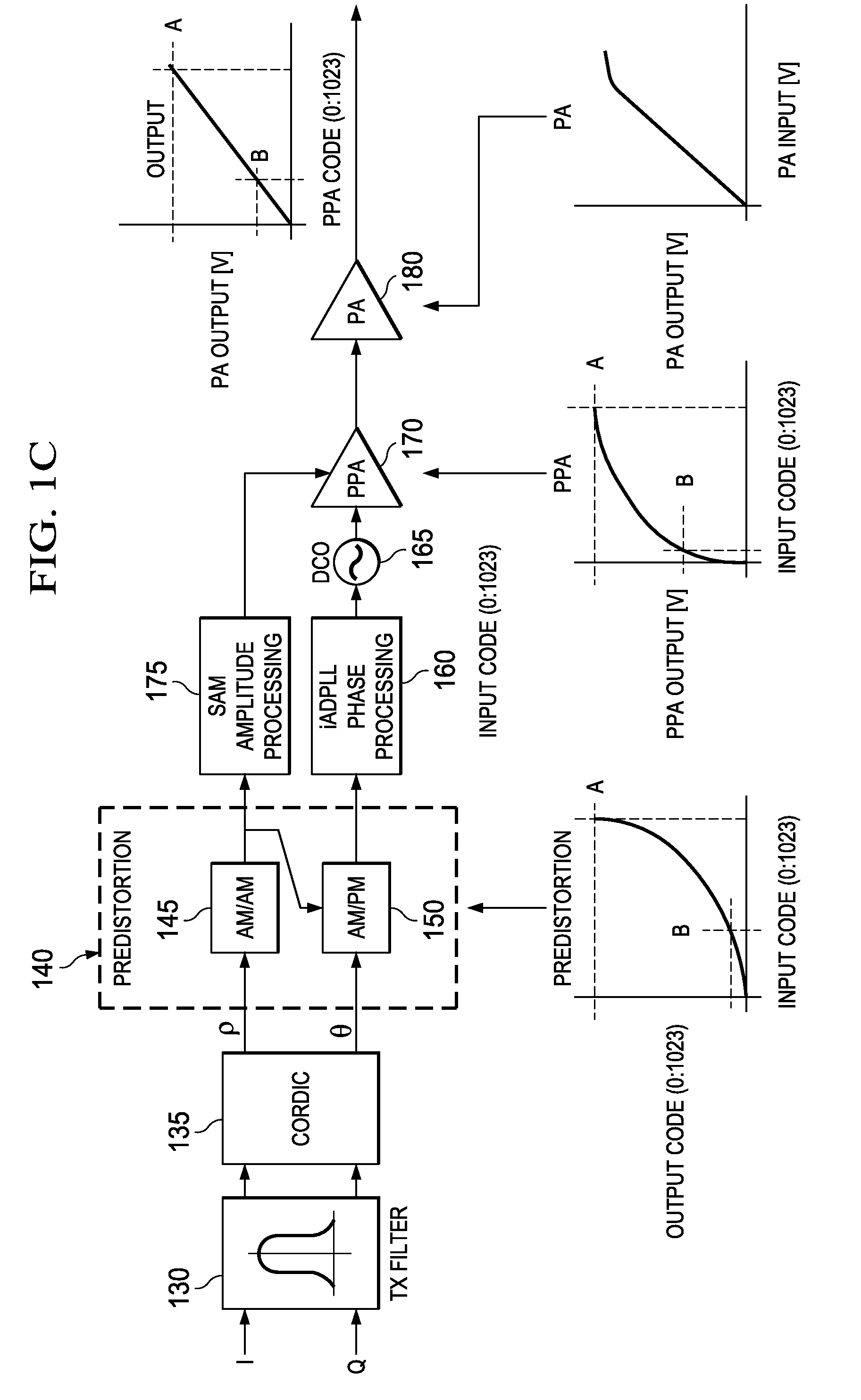
[0012]In another embodiment, the WCDMA transmitter includes: (1) a transmit chain having a predistorter configured to employ first amplitude and phase calibration and compensation LUTs to carry out predistortion in the transmit chain, a pre-power amplifier coupled to the predistorter and a power amplifier coupled to the pre-power amplifier, (2) a receiver coupled to the transmit chain, (3) predistortion compensation circuitry associated with the receiver and configured to update second amplitude and phase compensation LUTs associated therewith based on at least one signal from at least one of the pre-power amplifier and the power amplifie...

Problems solved by technology

Unfortunately, highly linear amplifiers use relatively large amounts of power and numbers of highly accurate components, making them relatively power consumptive, large and expensive.
Though they perform the best, they are thus disfavored in many wireless applications, particularly those that require low-cost transmitters.
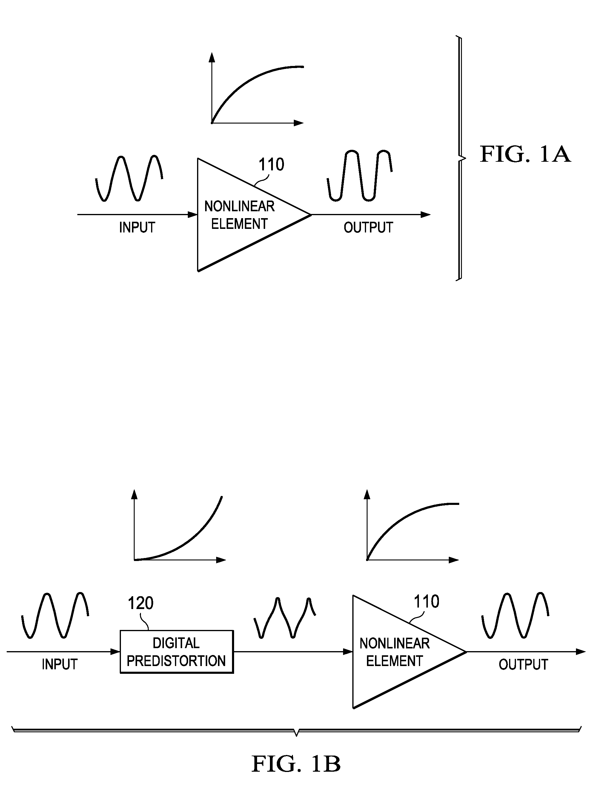
Though the amplifier then distorts the signal as it amplifies it, the predistortion and the amplifier distortion essentially cancel one another, resulting in an amplified, output signal having substantially reduced distortion.
Unfortunately, a factory-calibrated predistortion LUT often fails to linearize the amplifier(s) adequately under varying operational conditions (e.g., temperature, voltage, frequency and voltage standing-wave ratio, or VSWR).

Method used


Image

  • Apparatus and Method for Adaptive Polar Transmitter Linearization and Wireless Transmitter Employing the Same
  • Apparatus and Method for Adaptive Polar Transmitter Linearization and Wireless Transmitter Employing the Same
  • Apparatus and Method for Adaptive Polar Transmitter Linearization and Wireless Transmitter Employing the Same

Examples


Embodiment Construction

[0034]Various embodiments of a predistortion technique for a polar transmitter will be described herein. Certain embodiments are directed to on-line, indirect learning adaptation predistortion techniques. Certain embodiments of the on-line, indirect learning adaptation predistortion technique are appropriate for a 3G (e.g., WCDMA or UMTS) polar transmitter. Of course, the technique is also applicable to 2G and 4G polar transmitters, among others. In one embodiment to be illustrated and described, the predistortion LUT that is located in the transmit chain is divided into a calibration (static) LUT and a compensation (adaptive) LUT. An adaptation algorithm determines an update to a second compensation LUT in a shadow memory. The second compensation LUT is then used in a subsequent timeslot (perhaps by a simple memory pointer change), while the (first) compensation LUT that was active in the previous timeslot is now used to compute compensation under operational transmit characteristi...


PUM


Abstract

A polar transmitter and a method of linearizing a polar transmitter. In one embodiment, the transmitter includes: (1) a transmit chain having a predistorter configured to employ first amplitude and phase compensation lookup tables to carry out predistortion in the transmit chain, (2) a receiver coupled to the transmit chain and (3) predistortion compensation circuitry associated with the receiver and configured to update second amplitude and phase compensation lookup tables associated therewith based on at least one signal from the transmit chain, the values in the updated second amplitude and phase compensation lookup tables thereby available for subsequent predistortion.

Description

CROSS-REFERENCE TO PROVISIONAL APPLICATION[0001]This application claims the benefit of U.S. Provisional Application Ser. No. 60 / 957,119, filed by Waheed, et al., on Aug. 21, 2007, entitled “Method and Apparatus for Adaptive Polar Memoryless Transmitter Linearization,” commonly assigned with the invention and incorporated herein by reference.TECHNICAL FIELD OF THE INVENTION[0002]The invention is directed, in general, to wireless transmitters and, more specifically, to an apparatus and method for adaptive polar transmitter linearization and a wireless transmitter employing the apparatus or the method.BACKGROUND OF THE INVENTION[0003]Many applications exist for battery-powered, digital wireless transmitters, primarily in cellular communications systems such as those operating under the International Telecommunication Union's Wideband Code Division Multiple Access (WCDMA) standard. Such transmitters use one or more amplifiers, such as a digital pre-power amplifier (PPA) that feeds into ...

Claims


Application Information

Patent Timeline
IPC IPC(8): H04B15/00
CPCH04B2001/0425H04B1/0475H03F1/3241
Inventor WAHEED, KHURRAMBA, SEYDOU N.
Owner TEXAS INSTR INC
Learn More