Method And Apparatus For Register Renaming Using Multiple Physical Register Files And Avoiding Associative Search

a physical register and register renaming technology, applied in the field of method and register renaming, can solve the problems of affecting processor performance, ambiguity of all memory references at compile time, and high cost of counter-based physical register solutions, so as to avoid associative searching

Inactive Publication Date: 2009-02-26
INT BUSINESS MASCH CORP
View PDF11 Cites 27 Cited by
  • Summary
  • Abstract
  • Description
  • Claims
  • Application Information

AI Technical Summary

Problems solved by technology

Some of these factors include data dependencies between instructions as specified by semantics of a program, a finite number of architected registers determined by an instruction set architecture (ISA), and an inability to disambiguate all memory references at compile time by limiting an amount of instruction-level parallelism (ILP) that is exposed through program binaries.
These false dependencies affect processor performance because it forces serialized execution of instructions.
This counter-based physical register solution is an expensive solution that is not desirable.
The complexity and power consumed by the logic structures used for implementing such associative search functions is one of the major inhibitors for implementing high frequency out-of-order superscalar processors.
However, having a separate mapper (register renaming unit) for each type of registers is expensive, making it unattractive for wide-issue high-frequency superscalar processor designs.
As evident from the above discussion, conventional methods have limitations or inefficiencies, requiring a different approach to efficiently manage the renaming operations in an out-of-order superscalar processor.
Thus, it is well known that renaming registers affects effective utilization of resources in modern processors.

Method used


Image

  • Method And Apparatus For Register Renaming Using Multiple Physical Register Files And Avoiding Associative Search
  • Method And Apparatus For Register Renaming Using Multiple Physical Register Files And Avoiding Associative Search
  • Method And Apparatus For Register Renaming Using Multiple Physical Register Files And Avoiding Associative Search

Examples


Embodiment Construction

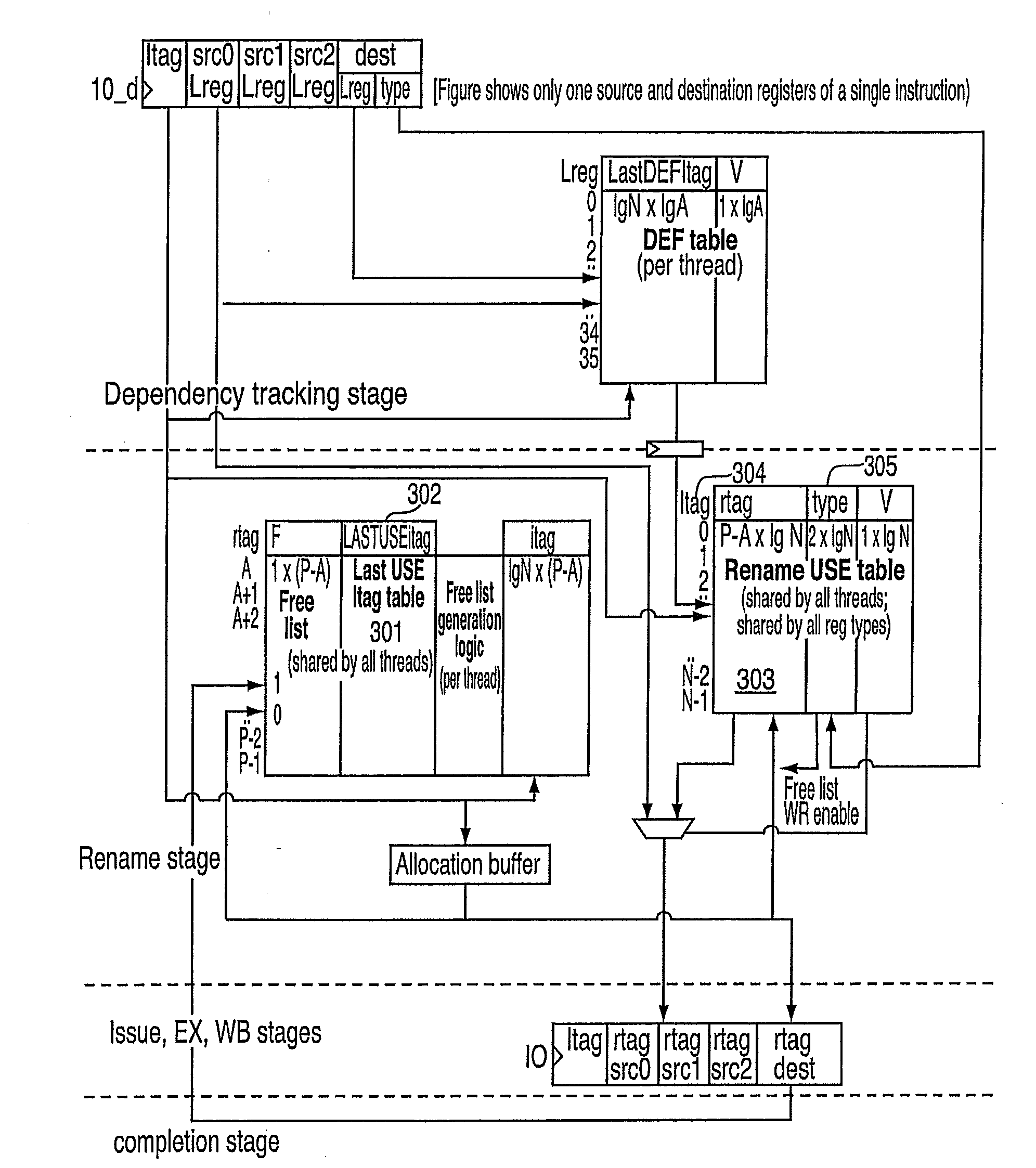
[0024]One aspect of the exemplary embodiments is a method for renaming registers. Another aspect of the exemplary embodiments is a method for reducing the complexity and size of register renaming hardware by using a shared mapping table indexed by instruction tags to store logical-to-physical register mapping for different types of logical registers (such as general-purpose or integer registers (GPRs), floating-point registers (FPRs), vector registers (VRs), etc.) used by multiple threads and avoiding associative searching.

[0025]The exemplary embodiments provide for a technique for implementing an area and power efficient renaming scheme for a digital data processor using multiple physical register files. The exemplary embodiments further provide for an improved pipeline processor design which exploits simple hardware structures for register renaming to execute instructions at a higher rate than known pipeline processors by enabling higher clock frequency processor designs. In addit...


PUM


Abstract

A method for implementing a register renaming scheme for a digital data processor using a plurality of physical register files for supporting out-of-order execution of a plurality of instructions from one or more threads, the method comprising: using a DEF table to store the instruction dependencies between the plurality of instructions using the instruction tags, the DEF table being indexed by a logical register name and including one entry per logical register; using a rename USE table indexed by the instruction tags to store logical-to-physical register mapping information shared by multiple sets of different types of non-architected copies of logical registers used by multiple threads; using a last USE table to transfer data of the multiple sets of different types of non-architected copies of logical registers into the first set of architected registered files, the last USE table being indexed by a physical register name in the second set of rename registered files; and performing the register renaming scheme at the instruction dispatch or wake-up / issue time.

Description

CROSS REFERENCE TO RELATED APPLICATIONS[0001]This application is a continuation of U.S. patent application Ser. No. 11 / 456,878 filed Jul. 12, 2006, the contents of which are incorporated by reference herein in their entirety.TRADEMARKS[0002]IBM® is a registered trademark of International Business Machines Corporation, Armonk, N.Y., U.S.A. Other names used herein may be registered trademarks, trademarks or product names of International Business Machines Corporation or other companies.GOVERNMENT INTEREST[0003]This invention was made with Government support under contract No.: NBCH3039004 awarded by Defense Advanced Research Projects Agency (DARPA). The Government has certain rights in this invention.BACKGROUND OF THE INVENTION[0004]1. Field of the Invention[0005]This invention relates to digital data processing systems, and particularly to a renaming scheme used for supporting out-of-order speculative execution of instructions.[0006]2. Description of Background[0007]There are many fa...

Claims


Application Information

Patent Timeline
Patent Type & Authority Applications(United States)
IPC IPC(8): G06F9/30
CPCG06F9/3838G06F9/3851G06F9/384
Inventor BURKY, WILLIAM E.KAILAS, KRISHNAN K.SINHAROY, BALARAM
Owner INT BUSINESS MASCH CORP
Why Eureka
Try Eureka