
Protection vacuum gate valve

Inactive Publication Date: 2009-03-05
STS
View PDF4 Cites 5 Cited by
  • Summary
  • Abstract
  • Description
  • Claims
  • Application Information

AI Technical Summary

Benefits of technology

[0025]As described above, according to the present invention, a flow control groove is formed at a portion contacting with a slide space at both upper sides of a second body, so that it is possible to prevent a corrosion of a fluid passage sealing member as fluid is inputted into a slide space. It is possible to control the flow when fluid flows from a chamber to a vacuum pump without forming an auxiliary fluid tube.
[0026]In addition, a sealing plate is made thinner and simpler, so that a manufacturing work is easy, and the cost decreases.
[0027]An elastic part is provided at an upper side of the sealing plate, so that it is possible to open and close a main fluid passage when a sealing plate moves as a corrosion prevention sealing member moves up and down.

Problems solved by technology

However, when fluid is inputted into the main fluid passage 11 as the conventional vacuum gate valve is open, it is needed to install the auxiliary fluid tube 16 and the auxiliary fluid tube 17 so as to control the flow of fluid which moves from the chamber to the vacuum pump, the manufacture process of the valve and the cost are increased.
In addition, it is needed to additionally provide a tube diameter control valve 70 so as to control the diameter of the auxiliary fluid tube 17, so that the whole construction is complicated.
When the valve is abruptly opened, the valve may be damaged owing to the pressure difference between the chamber and the vacuum pump.

Method used


Image

  • Protection vacuum gate valve
  • Protection vacuum gate valve
  • Protection vacuum gate valve

Examples


Embodiment Construction

[0038]The present invention will be described with reference to the accompanying drawings. The same reference numerals of the drawings represent the same elements.

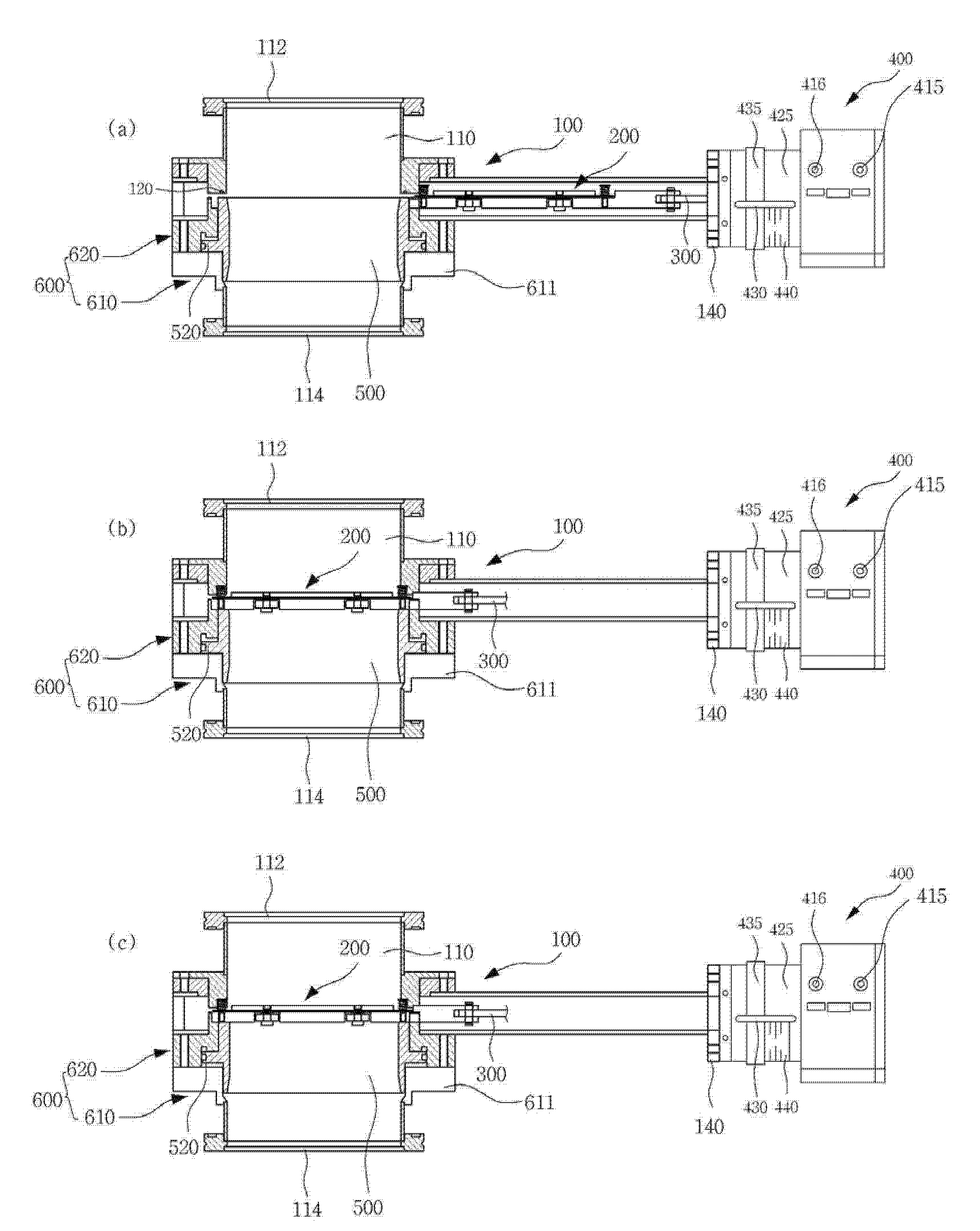
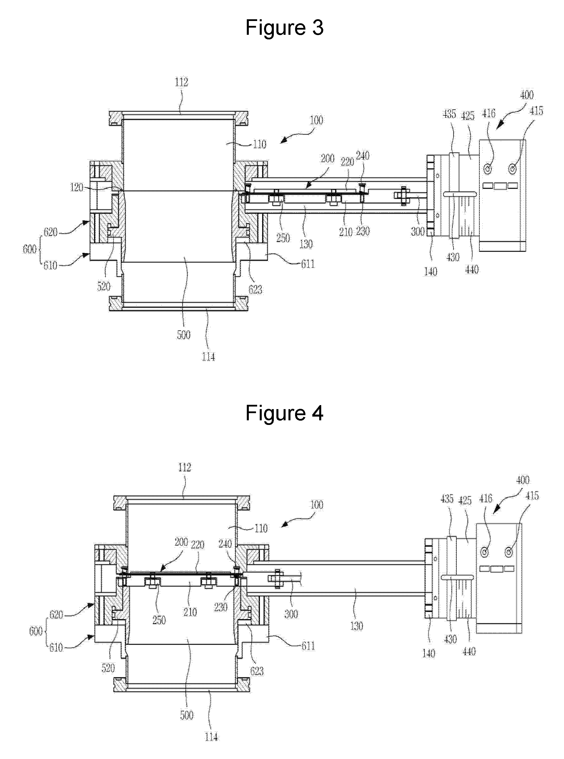
[0039]FIG. 3 is a side view of a state when a fluid passage sealing member of a corrosion prevention vacuum gate valve is open according to an embodiment of the present invention. FIG. 4 is a side view of a state when a fluid passage sealing member of a corrosion prevention vacuum gate valve is closed according to an embodiment of the present invention.

[0040]As shown in FIGS. 3 and 4, the corrosion prevention vacuum gate valve according to a preferred embodiment of the present invention comprises a housing 100, a fluid passage sealing member 200, a link 300, a first actuator 400, a corrosion prevention sealing member 500 and a second actuator 600.

[0041]The housing 100 comprises a main fluid passage 110, and a slide space 130.

[0042]The main fluid passage 110 comprises an inlet 112 formed at its one side and connected with a...


PUM


Abstract

The present invention relates to an improved vacuum gate valve for a corrosion prevention. The corrosion prevention vacuum gate valve comprises a second actuator which includes a hollow first body which has a second compression air inlet for moving up the corrosion prevention sealing member and a hollow second body which has a third compression air inlet moving down the corrosion prevention sealing member and at least one flow control groove which is provided at the upper side for moving the fluid from the chamber to the vacuum pump.

Description

CROSS REFERENCES[0001]Applicant claims priority under Patent Cooperation Treaty and 35 U.S.C. § 371 to International Application No. PCT / KR2006 / 005728 filed Dec. 27, 2006 which claims foreign priority under Paris Convention to Korean Patent Application No. 10-2006-0009691, filed Feb. 1, 2006 with the Korean Intellectual Property Office.TECHNICAL FIELD[0002]The present invention relates to an improved vacuum gate valve for a corrosion prevention, and in particular to an improved vacuum gate valve for a corrosion prevention in which it is possible to prevent a corrosion of a fluid passage sealing member as fluid is inputted into a slide space by providing a flow control groove at a portion contacting with a slide space at both upper sides of a second body, and it is possible to control the flow without forming an auxiliary fluid tube when fluid flows from a chamber to a vacuum pump.BACKGROUND ART[0003]Generally, a semiconductor requires a high accuracy, so that a reliable cleanness an...

Claims


Application Information

Patent Timeline
IPC IPC(8): F16K25/04F16K3/30
CPCF16K51/02F16K25/04F16K3/02F16K3/314F16K27/04
Inventor JI, JONG-WOO
Owner STS
Features
  • Generate Ideas
  • Intellectual Property
  • Life Sciences
  • Materials
  • Tech Scout
  • Unparalleled Data Quality
  • Higher Quality Content
  • 60% Fewer Hallucinations
Learn More