Rotor of brushless direct-current motor

a brushless direct-current, motor technology, applied in the direction of dynamo-electric machines, magnetic circuit rotating parts, magnetic circuit shape/form/construction, etc., can solve the problem of unavoidable transfer of electromagnetic vibration noise of rotating magnetic field, resonance noise, cogging torque vibration due to interaction with armature core,

Inactive Publication Date: 2009-03-05
JEUNG YOUNG CHUN
View PDF4 Cites 11 Cited by
  • Summary
  • Abstract
  • Description
  • Claims
  • Application Information

AI Technical Summary

Benefits of technology

[0016]Accordingly, an aspect of the embodiments discussed herein has been made in view of the above-mentioned problems occurring in the prior art, and it is an object of the present invention to provide a rotor of a BLDC motor, in which a permanent magnet of the rotor is formed integrally in a ring shape as one piece and has a magnetic circuit therein, thereby removing a need for a ferromagnetic for a separate magnetic circuit through which the magnetic flux of the permanent magnet can pass.

Problems solved by technology

However, when the permanent-magnet rotor generates a rotation torque due to its interaction with a rotating magnetic field of an armature, electromagnetic cogging generated in an air gap between the rotor and the armature, torque ripple, or vibration caused by the interaction of electromagnetism is directly transferred to the rotor shaft and may be then transferred to the load side or may be amplified, thereby causing severe mechanical noise such as resonance noise.
Such vibration is directly transferred up to a load side through the rotor shaft 14, thereby amplifying mechanical vibration noise or causing resonance noise during the motor driving and increasing stress in a bearing while aggravating bearing noise, thus reducing the expected life span of a motor.
As a result, cogging torque vibration due to interaction with an armature core and electromagnetic vibration noise of the rotating magnetic field are unavoidably transferred to a load side through the motor rotary shaft.

Method used


Image

  • Rotor of brushless direct-current motor
  • Rotor of brushless direct-current motor
  • Rotor of brushless direct-current motor

Examples


Embodiment Construction

[0030]Reference will now be made in detail to the embodiments, examples of which are illustrated in the accompanying drawings, wherein like reference numerals refer to the like elements throughout. The embodiments are described below by referring to the figures.

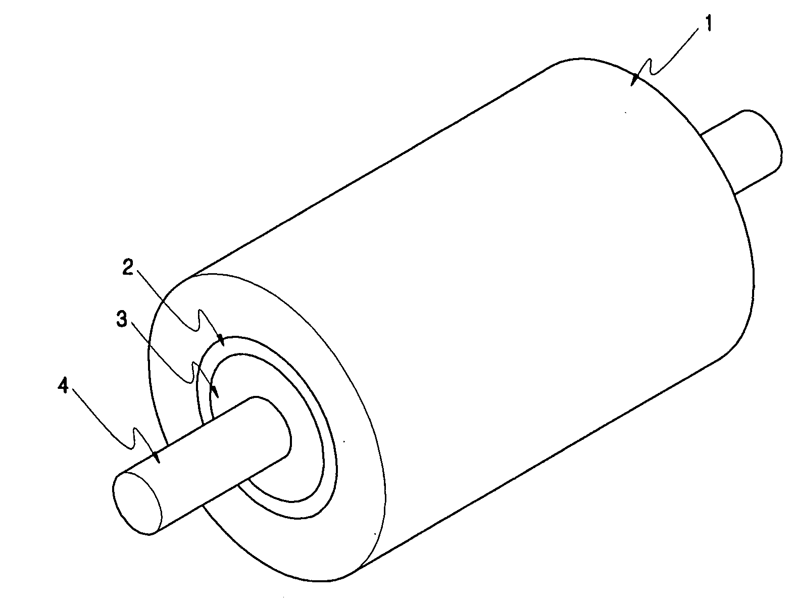
[0031]FIG. 3 illustrates the structure of a rotor of a BLDC motor. As illustrated in FIG. 3, the rotor includes a cylindrical permanent magnet 1 and a cylindrical high-strength core portion 2 made of aluminum having a very low thermal expansion coefficient, alloy, or high-strength engineering plastic, which is adhered to the inner circumferential portion of the permanent magnet 1.

[0032]It is preferable that in an embodiment the thickness of the high-strength core portion 2 can be 40-100% of that of the permanent magnet 1.

[0033]In the rotor of an embodiment, the cylindrical high-strength core portion 2 is inserted and adhered to an inner circumferential portion of the polar anisotropic permanent magnet 1, a sound-absorbing res...


PUM


Abstract

A permanent magnet rotor of a brushless direct current (BLDC) motor, in which cogging torque ripple and electromagnetic vibration noise transferred to the permanent magnet rotor can be blocked and a motor's power-to-weight ratio can be improved. A conventional BLDC motor has to use an electric steel sheet core so as to maintain the maximum magnetic flux density of the permanent magnet rotor and to minimize a rotating electric field loss. As a result, cogging torque vibration is unavoidably transferred to a load side through the motor rotary shaft. However, the rotor can enable stable driving of the BLDC motor by innovatively blocking the cogging torque vibration and the electromagnetic vibration noise and can greatly reduce the motor's weight by using a plastic or non-magnetic material instead of an electric steel sheet core.

Description

BACKGROUND[0001]1. Field[0002]One or more aspects of the embodiments discussed herein relates to a rotor of a brushless direct-current (hereinafter, referred to as “BLDC”) motor, and more particularly, to a rotor of an BLDC motor, which can prevent electromagnetic vibration and noise generated between a rotor and an armature from being transferred to a rotary shaft of the rotor during the motor driving to thereby minimize motor noise and can reduce the weight of the rotor to thereby maximize a motor's power-to-weight ratio.[0003]2. Description of the Related Art[0004]Generally, a conventional rotor of a brushless direct-current (BLDC) motor uses a permanent magnet and a rotor core is necessarily combined with a rotor shaft using a ferromagnetic body or an electric steel sheet in order to form a magnetic circuit of the permanent magnet.[0005]However, when the permanent-magnet rotor generates a rotation torque due to its interaction with a rotating magnetic field of an armature, elect...

Claims


Application Information

Patent Timeline
Patent Type & Authority Applications(United States)
IPC IPC(8): H02K5/24H02K1/27
CPCH02K1/30H02K1/2733
Inventor JEUNG, YOUNG-CHUN
Owner JEUNG YOUNG CHUN
Why Eureka
Try Eureka