
Planetary geared motor and dynamo

Inactive Publication Date: 2009-03-05
VENERA LAB CO LTD
View PDF3 Cites 10 Cited by
  • Summary
  • Abstract
  • Description
  • Claims
  • Application Information

AI Technical Summary

Benefits of technology

[0011]A third issue to be addressed by the present invention is to make use of the characteristic of the motor of the present invention, such that a free positional relation can be provided between the rotor and an armature in accordance with the arrangement, applied portion, and purpose of the motor, the position and angle of the rotation shaft can be varied freely without greatly influencing the rotation efficiency, and the motor can be designed freely to enable shifting of rotational speeds at a constant voltage and the like.
[0013]The present invention provides a simple structure which uses an armature, in which a toroidal coil is wound around a slotless annular iron core, to rotate a bipolar inner magnet rotor having a rotation diameter smaller than the inner diameter of the armature core at high speed.

Problems solved by technology

For each reverse rectification of the DC current, a dead point in which the rotation force is not generated is formed to cause uneven rotation and accordingly limit the starting position.
The surge voltage, the cogging torque, and the dead point are causes of electromagnetic noise generated from an armature of a DC motor.
In the conventional motor, since the positional relation of a rotor and a stator is limited and fixed, a rotation shaft cannot be designed in a free position and angle inside a motor mechanism, whereby the function, shape, and connection application method of an entire mechanical device requiring rotational torque of the motor are accordingly limited.

Method used


Image

  • Planetary geared motor and dynamo
  • Planetary geared motor and dynamo
  • Planetary geared motor and dynamo

Examples


Embodiment Construction

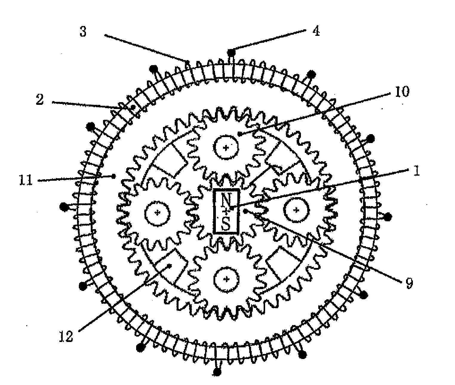
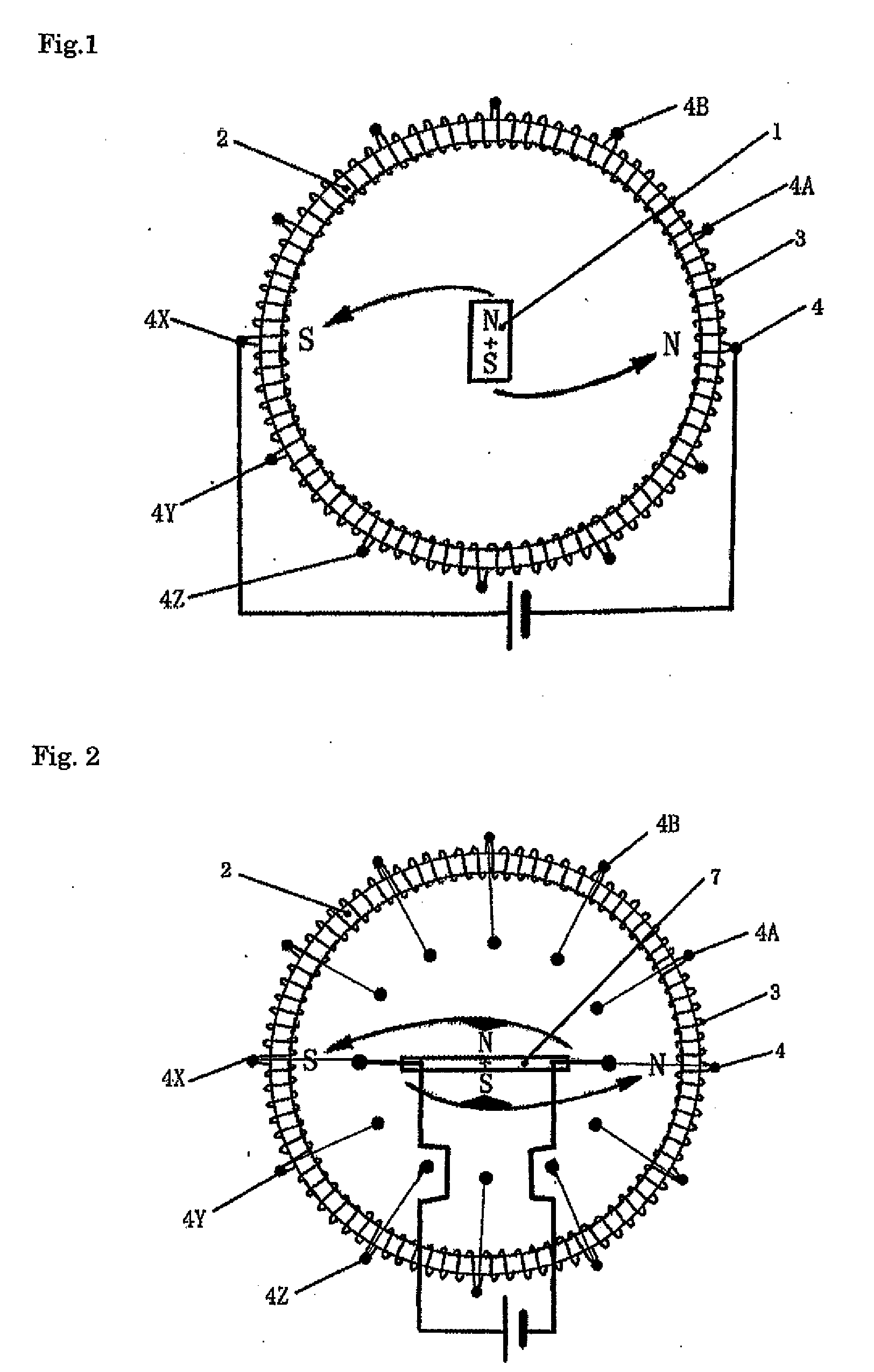
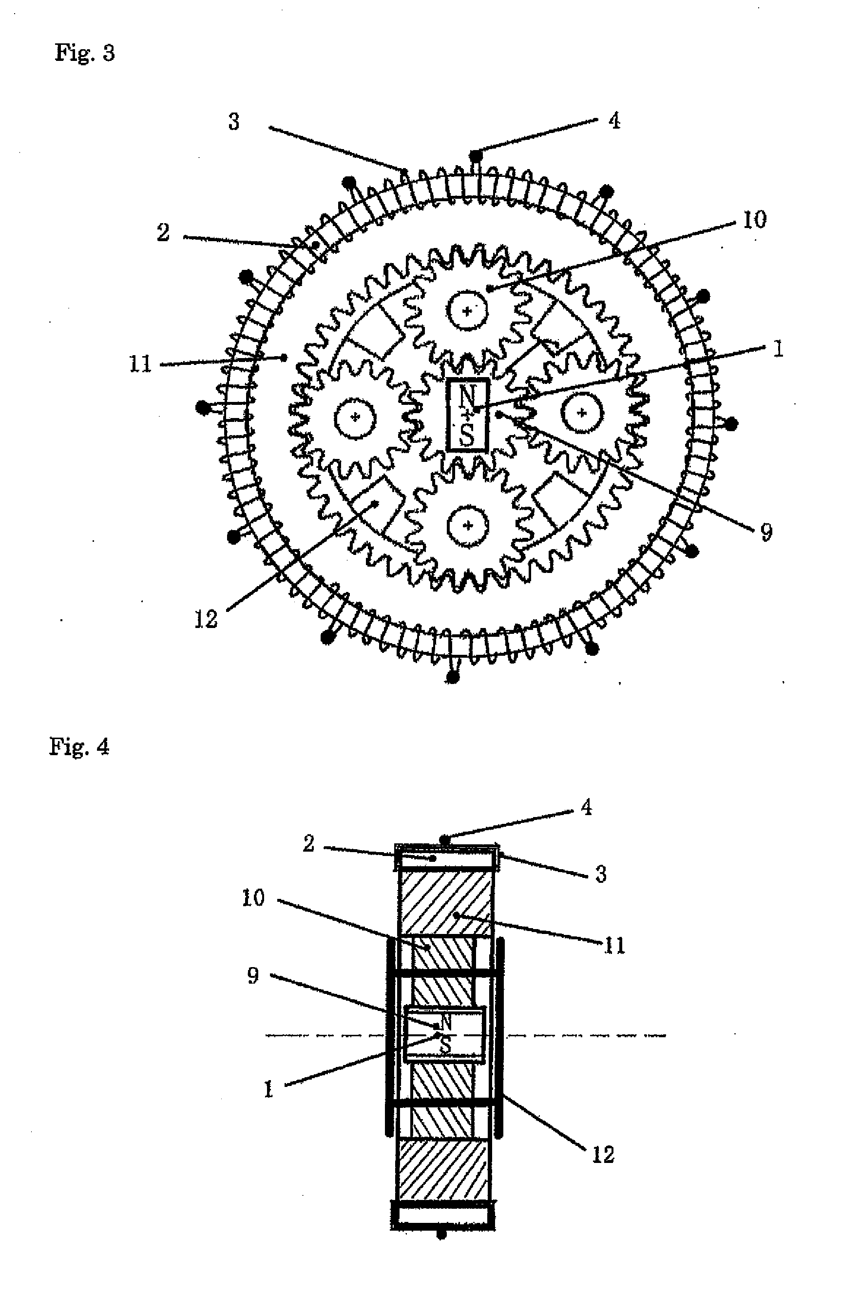
[0059]FIG. 1 is a view showing the relation of an armature stator and a magnet rotor of a bipolar DC motor which forms the basis of the present invention. Twelve layer-wound toroidal coils 3 are arranged at equal intervals around the entire circumference of a slotless annular iron core 2, and are respectively connected in series. The closed annular toroidal coil 3 is formed with the connection part thereof as an input terminal 4 of electric power.

[0060]Regarding the generation of rotational torque, DC voltage is applied to one of the input terminals of the armature stator, which is in a range where the rotation angle is in the rotational direction with respect to magnetic poles of a magnetic field of a magnet orthogonal to a rotation shaft of a bipolar inner magnet rotor 1, among the input terminals at the plurality of connection portions of the toroidal coil 3, i.e., an input terminal 4 and to an input terminal 4X in the 180 degrees diagonal position in the drawing, and is sequenti...


PUM


Abstract

Provided is a DC motor capable of eliminating a DC current reverse rectification performed in a conventional DC motor and enabling rotation of maximum torque at all rotation angle and having a shape and a function for facilitating a combination with a speed change gear mechanism. Also provided is a planetary gear dynamo using the shape and the function of the present invention and capable of reducing inverse torque when the function is used as a generator.

Description

TECHNICAL FIELD[0001]The present invention relates to a combination of a gear transmission mechanism and a DC motor, and more specifically provides an electric generator, which is most appropriate to be combined with a gear mechanism and in which reverse torque due to an armature reaction is reduced by utilizing a bipolar DC motor and a planetary gear mechanism having novel shapes, performances, and functions.BACKGROUND ART[0002]In conventional technology called a geared motor, a rotation shaft of a motor and a gear mechanism are connected, and housings thereof are secured to each other by screws, as shown in Japanese Unexamined Patent Publication No. 2001-5425.[0003]Alternatively, a motor part and a gear mechanism part are arranged separately and connected by rotation shafts of a motor, and the motor part and the gear mechanism part are divided and held in one housing in the technology, as shown in Japanese Unexamined Patent Publication No. 2003-314634.[0004]Since a permanent magne...

Claims


Application Information

Patent Timeline
IPC IPC(8): H02K3/28F16H35/00
CPCH02K7/116H02K41/06H02K25/00H02K23/62H02K51/00
Inventor MIZUSHIMA, YASUO
Owner VENERA LAB CO LTD
Learn More