Wideband antenna unit

a wideband antenna and antenna technology, applied in the direction of resonant antennas, antenna earthings, elongated active element feeds, etc., can solve the problems of difficult antenna planning, difficult for the uwb to include a lot of frequency components to make the antenna resonate, etc., and achieve the effect of shrinking the size of the radiation elemen

Inactive Publication Date: 2009-03-05
MITSUMI ELECTRIC CO LTD
View PDF2 Cites 49 Cited by
  • Summary
  • Abstract
  • Description
  • Claims
  • Application Information

AI Technical Summary

Benefits of technology

[0028]Inasmuch as this invention is provided with a flat shaped radiation element on a plane flush with a plane in which a ground plate extends and the radiation element has an elliptic shape, this invention has the effect of shrinking the size of the radiation element in a case where a dielectric is not used.

Problems solved by technology

The antenna has a resonance frequency which is determined by its length, it is difficult for the UWB including a lot of frequency components to make the antenna resonate.
Accordingly, the wider the frequency band of the electric wave to be transmitted is, the more difficult it makes a plan for the antenna.

Method used


Image

  • Wideband antenna unit
  • Wideband antenna unit
  • Wideband antenna unit

Examples


Embodiment Construction

[0036]New, the description will be made as regards an embodiment of this invention in detail with reference to drawings.

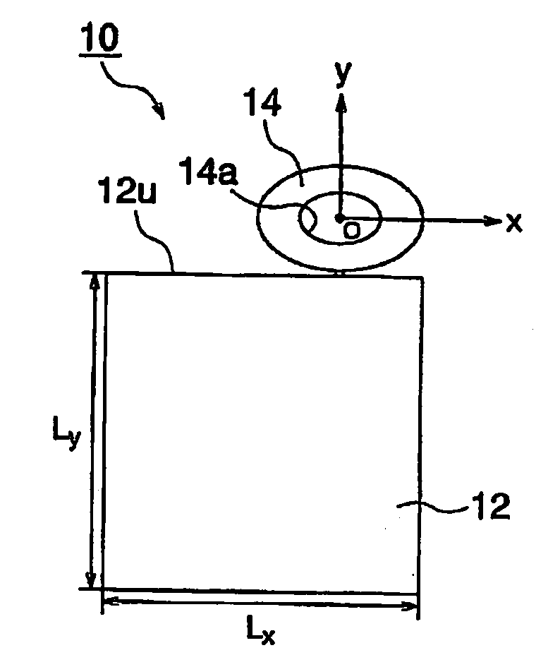
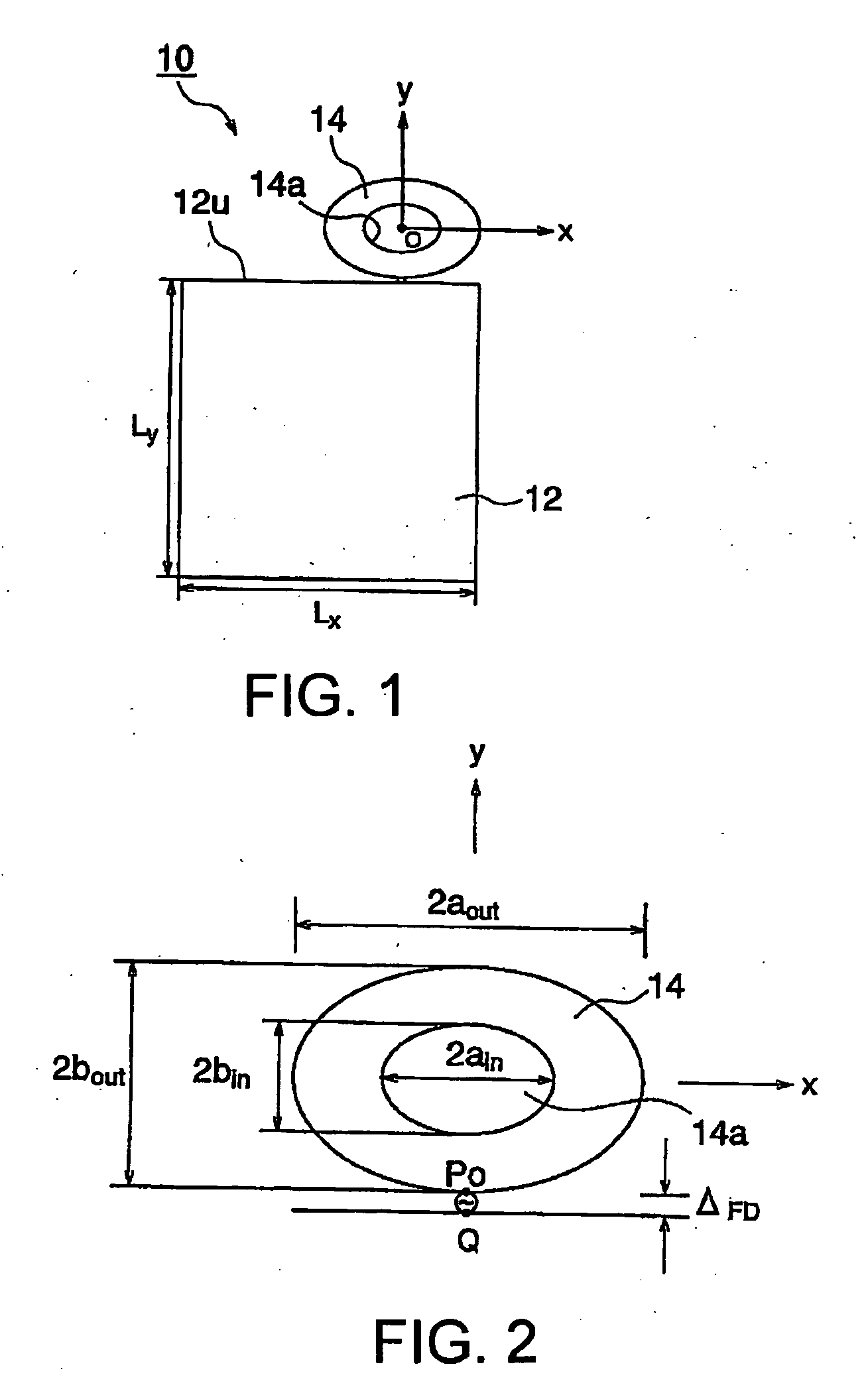
[0037]Referring to FIGS. 1 and 2, a wideband antenna unit 10 according to an embodiment of the present invention will be described. FIG. 1 is a plan view of the wideband antenna unit 10 while FIG. 2 is an enlarged plan view showing a radiation element 14 for use in the wideband antenna unit 10 illustrated in FIG. 1. The wideband antenna unit 10 comprises a ground plate 12 and a radiation element 14. Herein, as shown in FIG. 1, the origin point 0 is a center of radiation element 14, an x-axis extends sidewise (in a width direction; a horizontal direction) and a y-axis extends lengthwise (in a longitudinal direction; up and down).

[0038]The ground plate 12 has a rectangular shape which has a width (x-axis) of Lx and a length (y-axis) of Ly. In the example being illustrated, the width (x-axis) Lx is equal to 45 mm and the length (y-axis) Ly is equal to 45 mm. That is, ...


PUM


Abstract

To provide a thin wideband antenna unit capable of shrinking the size of a radiation element in a case where a dielectric is not used.
In a wideband antenna unit 10 having a ground plate 12 and a flat shaped radiation element 14 disposed on a plane (x, y) flush with a plane where the ground plate extends, the radiation element 14 has an elliptically shape. The radiation element 14 and the ground plate 12 are apart from each other by a predetermined feeding distance ΔFD. A ratio between an outside diameter 2aout in an ellipse's x-direction and an outside diameter 2bout in an ellipse's y-direction is 8:5. The elliptically shaped radiation element 14 has an elliptically shaped opening 14a which is concentric O with the elliptically shape. An inside diameter 2bin in the ellipse's y-direction is half of an outside diameter 2bout in the ellipse's y-direction. It is desirable that an inside diameter 2ain of the elliptically shaped opening 14a in the ellipse's x-direction is not more than half of the outside diameter 2aout in the ellipse's x-direction.

Description

TECHNICAL FIELD[0001]This invention relates to a wideband antenna unit and, more particular, to an antenna for a UWB (Ultra Wide band).BACKGROUND ART[0002]The UWB means an ultra wideband radio like its name and is a broad sense term referring to any radio transmission system that occupies a bandwidth greater than 25 percent of the center frequency, or a bandwidth equal to or more 1.5 GHz. In a word, it is technology for communicating using short pulses (normally of 1 ns or less) of ultra wideband so as to start a revolution in radio.[0003]A crucial difference between a conventional radio and the UWB is the presence or absence of a carrier wave. The conventional radio modulates a sinusoidal wave having a frequency called the carrier wave using various methods to transmit and receive data. On the other hand, the UWB does not the carrier wave. In the manner which is written in definition of the UWB, it uses the short pulses of the ultra wideband.[0004]Like its name, the UWB has a frequ...

Claims


Application Information

Patent Timeline
Patent Type & Authority Applications(United States)
IPC IPC(8): H01Q9/04
CPCH01Q1/48H01Q9/30H01Q9/40
Inventor NAKANO, HISAMATSUMIYOSHI, AKIRAKONDO, TAKAAKIHATTORI, SATOSHIYAMAUCHI, JUNJI
Owner MITSUMI ELECTRIC CO LTD
Why Eureka
Try Eureka