Imaging device and image processing apparatus

a technology of image processing and image processing, which is applied in the direction of color television details, television system details, television systems, etc., can solve the problems of increasing power consumption, requiring more memory, and unable to shoot motion images and still images with a proper exposure amount, so as to suppress random noise, reduce movement, and suppress fpn

Inactive Publication Date: 2009-03-05
XACTI CORP
View PDF2 Cites 36 Cited by
  • Summary
  • Abstract
  • Description
  • Claims
  • Application Information

AI Technical Summary

Benefits of technology

[0024]In the image processing apparatus, a movement detector (122) detects a movement of a feature point among the plurality of object scene images, and a first clipper (126) performs clipping processing on each of the plurality of object scene images at a position based on the detection result by the movement detector. That is, the clipping position of the first clipper moves according to the movement of the feature point. Thus, by making the clipping position follow the movement of the feature point, it is possible to reduce the movement among the plurality of object scene images.
[0025]Each of the plurality of object scene images after the first clipper is applied to the adder (128, 128A) so as to be subjected to adding processing of adding one or plurality of object scene images temporally proximate to the object scene image. By thus adding the proximate object scene images, it is possible to suppress the random noise included in each of the plurality of object scene images.
[0026]In addition, by arranging an adder at the back of the first clipper, it is possible to also suppress the FPN. By moving the clipping position, the FPN has a property as a random noise, and such a noise component is also suppressed by the adder.
[0027]Furthermore, in the adder, a divider (150a, 150b, 152a, 152b) divides a pair of the object scene images to be added with each other into a common partial image (B11-B66), and a weighted adder (154a, 154b, 156) weighs the division result by the divider with a coefficient for each common partial image and adds the results to each other. By determining the coefficient for weighting for a common partial image, it is possible to avoid a blur at a part with the large movement.

Problems solved by technology

However, even if the related arts are merely combined, it is difficult to shoot both of the motion images and still images with a proper exposure amount by accurately using two kinds of camera shake correction for motion image and still image.
However, merely combining the related arts with each other requires more memory and increases power consumption.
On the other hand, in the latter related art, the 3DDNR is performed only on the part with small movement, and therefore, the blur at the portion with large movement is avoided, but the dimension of the movement is determined by the unit of pixels, resulting in an enormous amount of throughputs.

Method used


Image

  • Imaging device and image processing apparatus
  • Imaging device and image processing apparatus
  • Imaging device and image processing apparatus

Examples


first embodiment

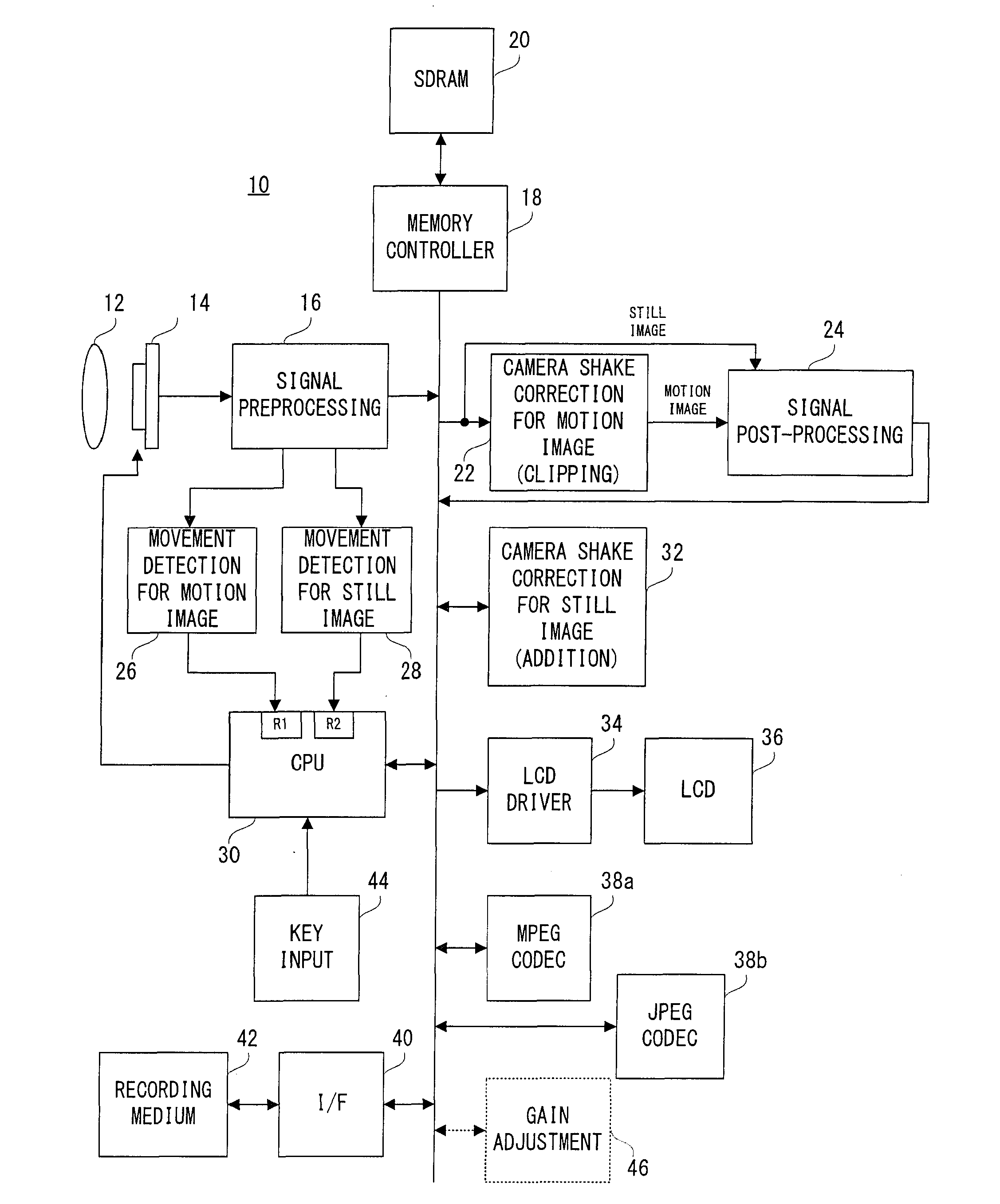
[0056]Referring to FIG. 1, a digital camera 10 according to this embodiment includes an image sensor 14. An optical image of an object scene passing through an optical lens 12 is irradiated onto an acceptance surface, that is, an imaging surface of the image sensor 14 on which electric charges corresponding to the optical image of the object scene, that is, a raw image signal is generated by photoelectronic conversion.

[0057]When a real-time motion image of the object scene, that is, a through-image is displayed on an LCD monitor 36, the CPU 30 instructs the image sensor 14 to repetitively perform an exposure and a reading. The image sensor 14 repetitively executes an exposure over an exposure time T and reading a raw image signal thus generated at a cycle of 1 / 60 seconds, for example. A raw image signal corresponding to the optical image of the object scene is output from the image sensor 14.

[0058]The output raw image signal is subjected to preprocessing such as an A / D conversion, a...

second embodiment

[0105]With reference to FIG. 8, the digital movie camera 100 in this embodiment includes an optical lens 112, an image sensor 114, a signal preprocessing circuit 116, an FPN correction circuit 118a, a line memory 118b, a DRAM 120, a movement detection circuit 122, a CPU 124, a first clipping circuit 126, a 3DDNR circuit 128, a signal post-processing circuit 130, a second clipping circuit 132, a display system circuit 134, a record system circuit 136, a flash memory 138 and a key input device 140.

[0106]Additionally, the image sensor 114 is preferably made up of a CMOS (Complementary Metal-Oxide Semiconductor), but may be made up of other image-pick-up devices, such as a CCD (Charge-Coupled Device), etc.

[0107]Out of these components, each of the FPN correction circuit 118a, the line memory 118b, the first clipping circuit 126 and the second clipping circuit 132 is turned on or off by the CPU 124 on the basis of the presence or absence of FPN, the ON / OFF state of the camera shake corre...


PUM


Abstract

An imaging device includes an imager, with which an optical image of an object scene is repetitively captured. A first movement detector detects, as to each of a plurality of object scene images according to a time series output from the imager, a movement of a first feature point between the object scene image and the object scene images immediately before, and a clipper performs clipping processing on each of the plurality of object scene images on the basis of the detection result. When a still image recording operation is performed, a CPU changes an exposure time of the imager in such a direction as to shorten the time, and a second movement detector detects a movement of a second feature point between the object scene image immediately after the recording operation (reference object scene image) and the three object scene images being successive thereto out of a plurality of object scene images, and an adder adds the respective three object scene images to the reference object scene image while displacing the same on the basis of the detection result.

Description

CROSS REFERENCE OF RELATED APPLICATION[0001]The disclosure of Japanese Patent Application Nos. 2007-223105, 2007-239282 and 2007-239283 are incorporated herein by reference.BACKGROUND OF THE INVENTION[0002]1. Field of the Invention[0003]The present invention relates to an imaging device and an image processing apparatus. More specifically, the present invention relates to an imaging device which electronically performs a camera shake correction, and an image processing apparatus which performs image processing, such as a camera shake correction, a noise reduction, etc. on a plurality of object scene images according to a time series that are captured by the image sensor.[0004]2. Description of the Related Art[0005](I) In relation to imaging devices of such a kind, in one related art, a still image is produced by displacing a plurality of images being continuous according to a time series and adding them to each other. In another related art, a motion image is produced by displacing ...

Claims


Application Information

Patent Timeline
Patent Type & Authority Applications(United States)
IPC IPC(8): H04N5/228
CPCH04N5/145H04N5/23232H04N5/23248H04N5/365H04N5/23267H04N5/357H04N5/23254H04N23/951H04N23/6811H04N23/68H04N23/683H04N25/60H04N25/67
Inventor KUROKAWA, MITSUAKI
Owner XACTI CORP
Why Eureka
Try Eureka