Image display device and method

a technology of image display and image, which is applied in the field of image display devices and image displaying methods, can solve the problems of motion blur, motion blur, and the drawback of lcds (liquid crystal displays), and achieve the effect of effective prevention of image quality deterioration

Active Publication Date: 2009-03-05
SHARP KK
View PDF17 Cites 50 Cited by
  • Summary
  • Abstract
  • Description
  • Claims
  • Application Information

AI Technical Summary

Benefits of technology

[0074]According to the present invention, if a first image signal and a second image signal different from the first image signal are combined and displayed, the image quality deterioration can effectively be prevented in the display part of the second image signal by not performing an interpolation process with motion compensation.
[0075]If a first ima...

Problems solved by technology

As compared to conventional cathode-ray tubes (CRTs) primarily used for realizing moving images, LCDs (Liquid Crystal Displays) have a drawback, so-called motion blur, which is the blurring of outline of a movement portion perceived by a viewer when displaying an image with movement.
Since the impulse response of the image displaying light has a temporal spread in the above hold-type display mode, temporal frequency characteristics are deteriorated along with spatial frequency characteristics, resulting in the motion blur.
That is...

Method used


Image

  • Image display device and method
  • Image display device and method
  • Image display device and method

Examples


fifth embodiment

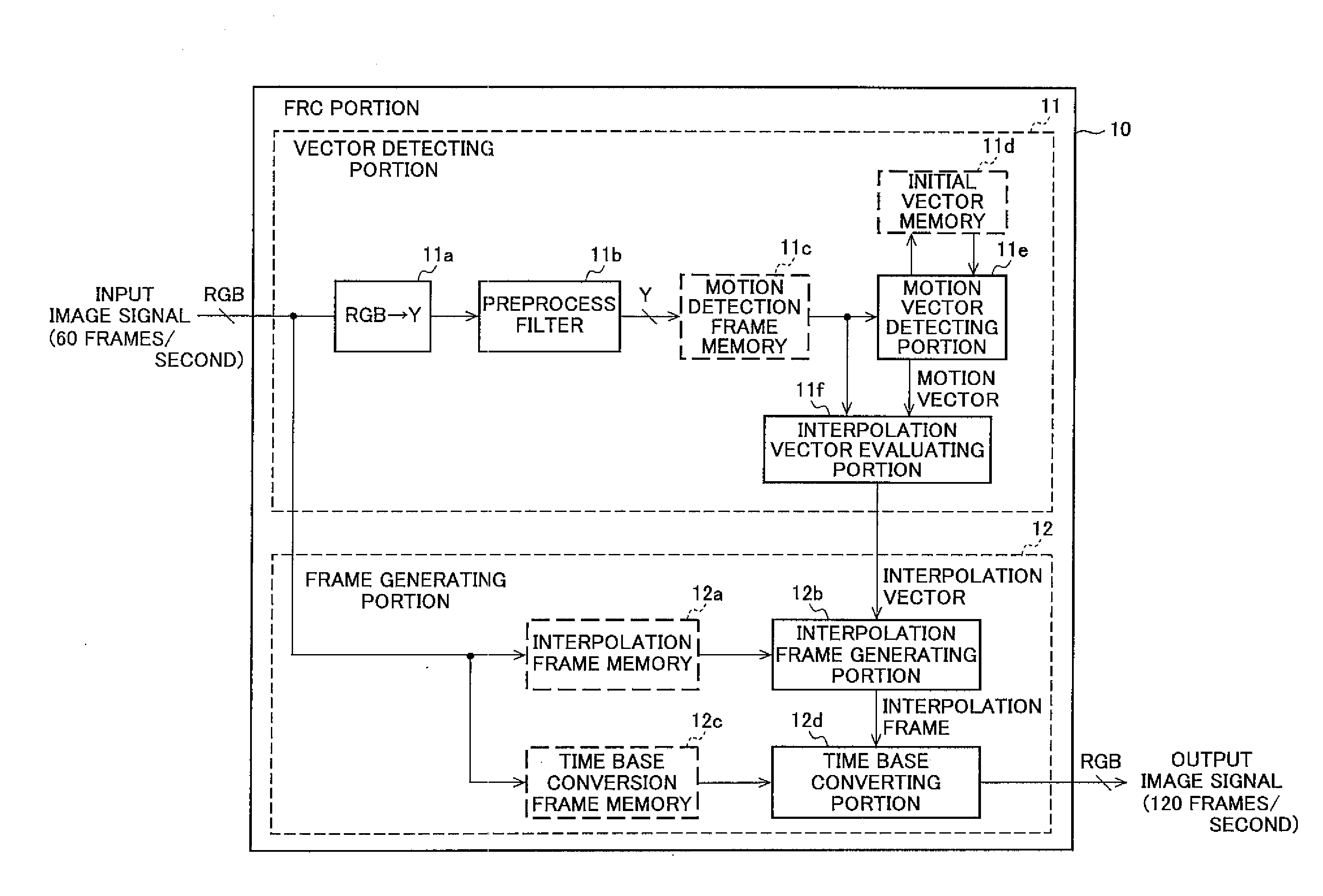
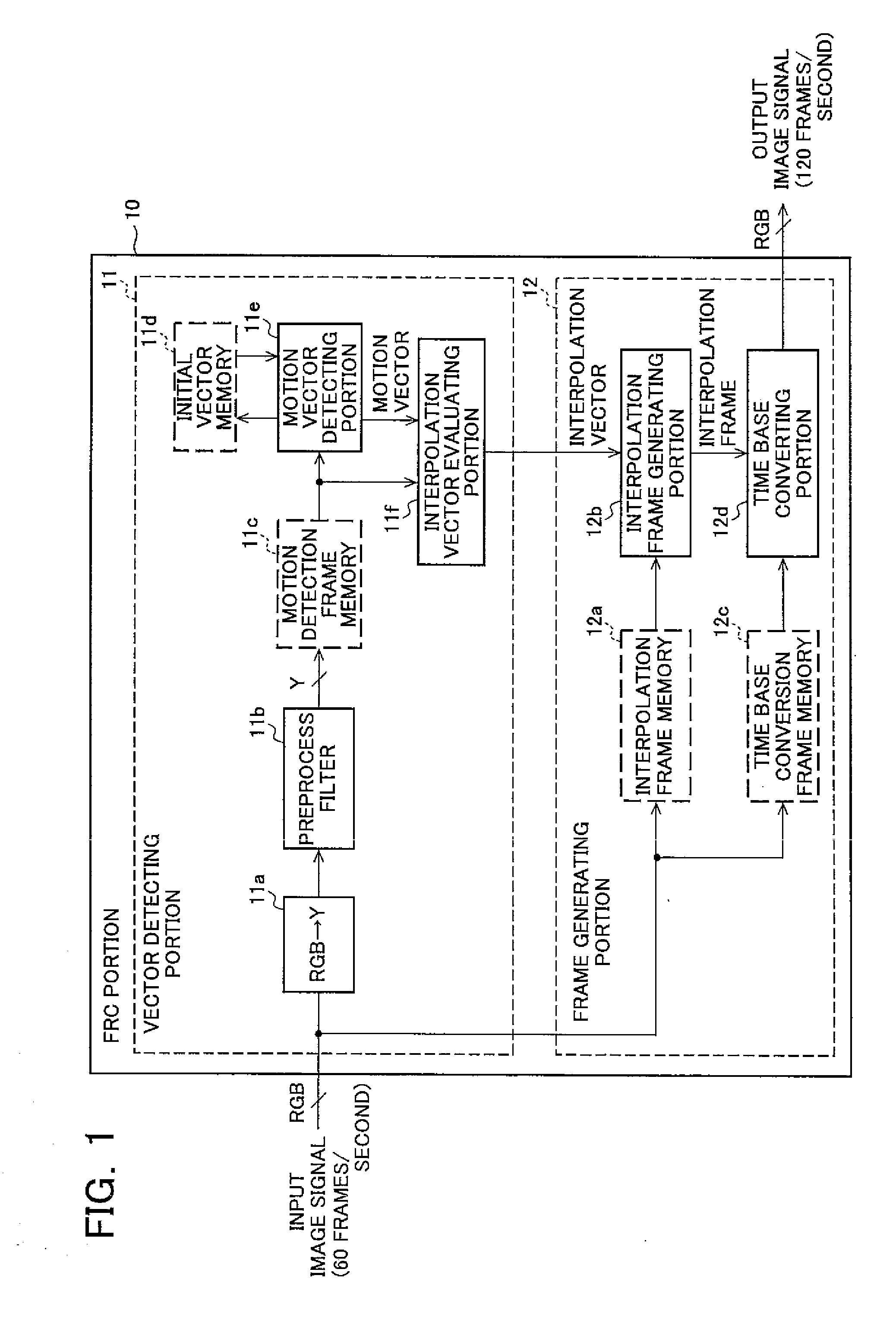
[0161]In a fifth embodiment of the present invention, a path is provided to bypass the FRC portion 10; it is assumed that the first image signal is, for example, the television image signal acquired by receiving broadcast and that the second image signal is, for example, the character signal such as OSD; and when both image signals are combined (overlapped) and displayed, the input image signal overlapped with the character signal is input to the path to change the drive frequency of the liquid crystal display panel 19 in conformity with the frame frequency of the input image signal. That is, if the image signal overlapped with the character signal is input, the switching is performed such that the input image signal overlapped with the character signal is directly displayed and output on the liquid crystal display panel 19 without performing the frame rate conversion.

[0162]FIG. 7 is a block diagram of an exemplary main configuration of a liquid crystal display device according to t...

sixth embodiment

[0168]In a sixth embodiment of the present invention, a path is provided to bypass the FRC portion 10; it is assumed that the first image signal is, for example, the television image signal acquired by receiving broadcast and that the second image signal is, for example, the sunscreen image signal such as PinP; and when both image signals are combined (overlapped) and displayed, the input image signal overlapped with the sub-screen image signal is input to the path to change the drive frequency of the liquid crystal display panel 19 in conformity with the frame frequency of the input image signal. That is, if the image signal overlapped with the sub-screen image signal is input, the switching is performed such that the input image signal overlapped with the sub-screen image signal is directly displayed and output on the liquid crystal display panel 19 without performing the frame rate conversion.

[0169]FIG. 9 is a block diagram of an exemplary main configuration of a liquid crystal d...

seventh embodiment

[0174]In a seventh embodiment of the present invention, a path is provided to bypass the FRC portion 10; it is assumed that the first image signal is, for example, the television image signal acquired by receiving broadcast and that the second image signal is, for example, the character signal such as OSD; and when both image signals are combined (overlapped) and displayed, the input image signal overlapped with the character signal is input to the bypass path to accumulate the input image signal in a memory on the path and the frame rate is converted by rapidly and repeatedly reading the image signal of the same frame from the memory more than once. That is, if the image signal overlapped with the character signal is input, the switching is performed such that the input image signal is rapidly and sequentially output to convert the frame rate and is displayed and output on the liquid crystal display panel 19 without performing the motion-compensated frame rate conversion.

[0175]FIG....


PUM


Abstract

In an image display device having a frame rate converting (FRC) portion, it is possible to prevent image degradation of a combined image display portion such as an OSD and PinP attributed to the FRC process. The image display device includes: an FRC portion 10 for converting the number of frames of an input image signal by interpolating an image signal subjected to a motion compensation process between the frames of the input image signal; an OSD processing portion 14 for superposing an OSD signal on the input image signal, and a controlling portion 15. The FRC portion 10 has a motion vector detecting portion 11e for detecting a motion vector between the frames of the input image signal, an interpolation vector evaluating portion 11f for allocating interpolation vector between frames based on the motion vector information, and an interpolation frame generating portion 12d for generating an interpolation frame from the interpolation vector. When the OSD signal is superposed on the input image signal, the controlling portion 15 disables the motion compensation process of the FRC portion 10 by making the motion vector detected by the motion vector detecting portion 11e 0 vector.

Description

TECHNICAL FIELD[0001]The present invention relates to an image display device and method including a function of converting a frame rate or field rate and, more particularly, to an image display device and an image displaying method of the device that prevent the image quality deterioration, in the case of combining and displaying a first image signal and a second image signal, in a display part of the first and second image signals due to a motion-compensated rate conversion process.BACKGROUND OF THE INVENTION[0002]As compared to conventional cathode-ray tubes (CRTs) primarily used for realizing moving images, LCDs (Liquid Crystal Displays) have a drawback, so-called motion blur, which is the blurring of outline of a movement portion perceived by a viewer when displaying an image with movement. It is suggested that this motion blur arises from the LCD display mode itself (see, e.g., patent document 1 and non-patent document 1).[0003]Since fluorescent material is scanned by an elect...

Claims


Application Information

Patent Timeline
IPC IPC(8): H04N7/01H04N5/445H04N5/45
CPCG09G3/20G09G2320/106G09G2340/0435G09G2340/125H04N5/145H04N5/44504H04N21/4435H04N7/013H04N7/014H04N21/4316H04N21/44008H04N21/440281H04N5/45
Inventor HANAOKA, TOSHIHARUYAMAMOTO, KENICHIROHFURUKAWA, HIROYUKIUENO, MASAFUMIYOSHIDA, YASUHIRO
Owner SHARP KK
Why Eureka
Try Eureka