Protective enclosure for personal electronic devices

a protective enclosure and electronic device technology, applied in the field of small personal electronic devices, can solve the problems of affecting the aesthetics, the compactness and aesthetics of electronic devices, and the bulky carrying cases, and achieves the effects of easy interchangeability, high strength, impact resistance and aesthetics

Inactive Publication Date: 2009-03-05
TAYLOR ALAN R
View PDF29 Cites 24 Cited by
  • Summary
  • Abstract
  • Description
  • Claims
  • Application Information

AI Technical Summary

Benefits of technology

[0012]It is therefore an object of this disclosure to provide a protective housing for small compact electronic devices which is thin and streamlined and does not detract from the small compact aesthetics of the electronic device.
[0013]Still another object of this disclosure is to provide an easily interchangeable protective housing for small electronic devices which facilitates attachment to articles of clothing, belts, arm bands, hanging from the neck, and the like.
[0014]Yet another object of this disclosure is to utilize thin-walled molded carbon fiber material for high strength, impact resistance and aesthetics to form a protective housing for electronic devices which are carried by the user or on the person's clothing or around the neck of the person and without substantially altering the compactness and aesthetics of the electronic device.

Problems solved by technology

However, to date, the only form of protection for these electronic devices from impact or abuse is in the form of a plastic, metal, vacuum formed, leather or leatherette carrying case available for such devices.
Such carrying cases are typically bulky, heavy, sometimes fragile and substantially diminish from the compactness and aesthetics of the electronic device.
Other limitations of the related art will become apparent to those skilled in the art upon a reading of the specification and a study of the drawings.

Method used


Image

  • Protective enclosure for personal electronic devices
  • Protective enclosure for personal electronic devices
  • Protective enclosure for personal electronic devices

Examples


Embodiment Construction

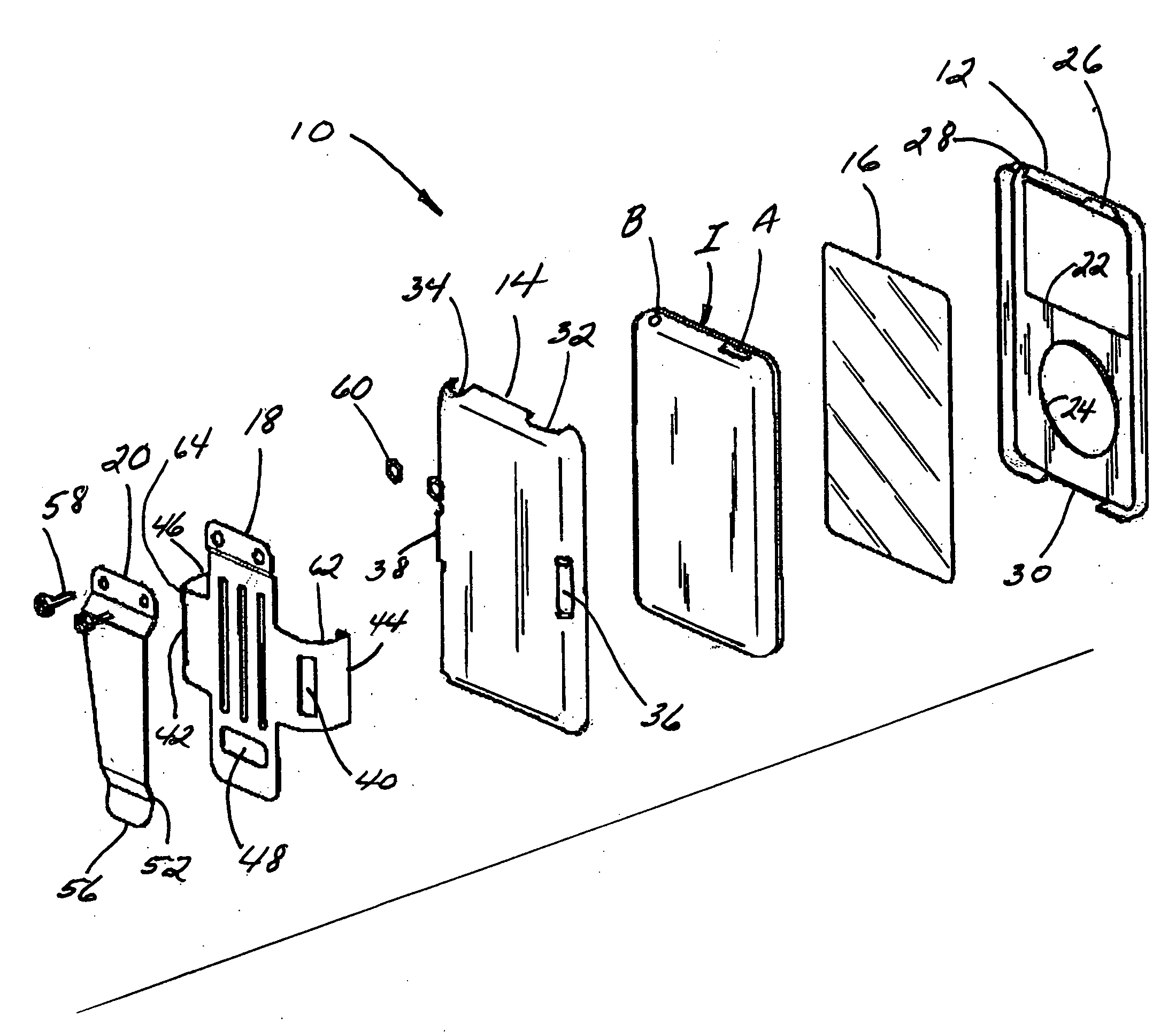
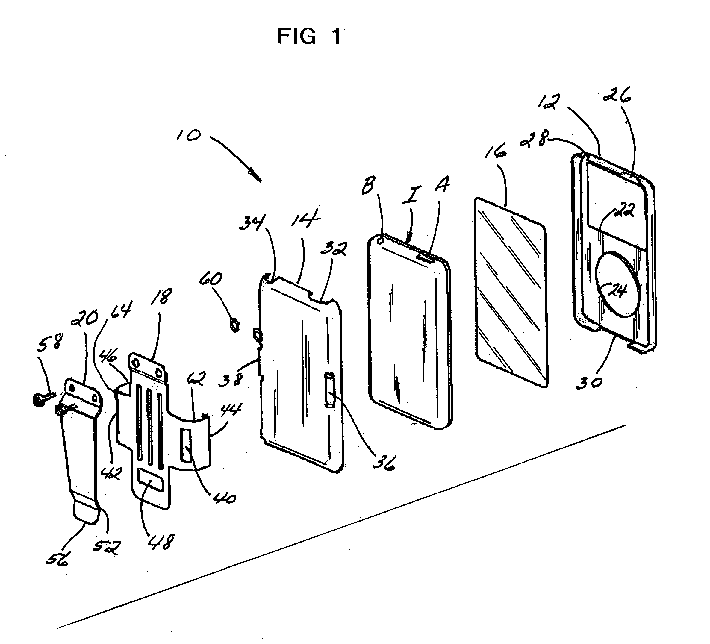
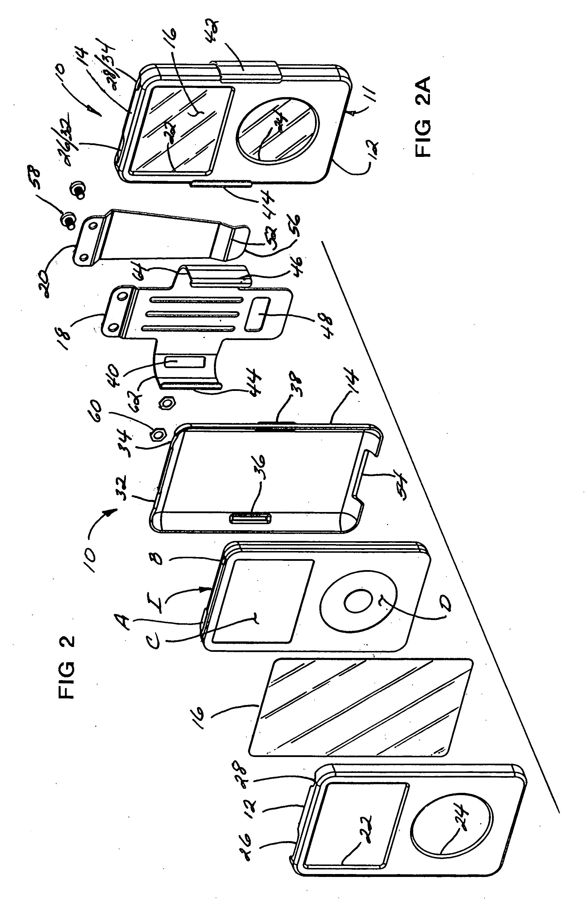
[0025]Referring now to the drawings, the preferred embodiment of the disclosure is there shown generally at numeral 10 and includes a housing 11 formed as a two-part unit of a front cover 12 and a back cover 14 which matably engage together along common mating edges therebetween. Each of these covers 12 and 14 are molded preferably of thin (0.06″ thick) carbon fiber material for both high impact strength and natural decorative effect. However, other decorative effects may be applied by, for example painting, or the utilization of pre-colored impact-resistant moldable material.

[0026]This device 10 is intended to protectively encase a small personal electronic device or pod shown generally at I preferably in the form of an APPLE IPOD music storage and playing device which includes a viewing screen C, a circular selector dial D and battery charging, antenna connector, and docking port terminals A, B and E, respectively. These personal electronic devices which may also include miniature...


PUM


Abstract

A protective enclosure for a small hand or body carryable personal electronic devices such as a well-known IPOD or IPHONE. A two-part generally rectangular housing includes front and back covers formed of high-impact thin-wall molded material and sized to protectively fit together along mating edges around the electronic device. Access openings are preferably provided for the viewing screen, control wheel, touch screen, battery charger, car phone plug-in, and docking port of the electronic device. A device clip formed of thin metal material having laterally extending retaining arms biasingly engage around opposing edges of front and back covers to hold them together against the front and back of the device. A belt clip may be connected to one end of the device clip adapted for releasable attachment to a clothing article.

Description

CROSS-REFERENCE TO RELATED APPLICATIONS[0001]Not applicableSTATEMENT REGARDING FEDERALLY SPONSORED RESEARCH OR DEVELOPMENT[0002]Not applicableINCORPORATION-BY-REFERENCE OF MATERIAL SUBMITTED ON A COMPACT DISC[0003]Not applicableBACKGROUND OF THE INVENTION[0004]1. Field of the Invention[0005]This invention relates generally to small personal electronic devices which are easily carryable in hand or attached around a user's neck or to the clothing or belt of a user and more particularly to a protective enclosure for such electronic devices which is easily installable and interchangeable.[0006]2. Description of Related Art[0007]Small electronic devices which are hand carryable or carried on an article of clothing, or belt, or around the neck of a user are well known. Such devices include the APPLE IPOD, I Phone, GPS, hand-held computer, cameras, laptops, small portable LCD televisions, cellular phones and the like. Advances in such electronic components have facilitated extreme compactn...

Claims


Application Information

Patent Timeline
Patent Type & Authority Applications(United States)
IPC IPC(8): H05K7/00
CPCH04B1/3816H05K7/14H04B1/3888
Inventor TAYLOR, ALAN R.
Owner TAYLOR ALAN R
Why Eureka
Try Eureka