Supercharge Your Innovation With Domain-Expert AI Agents!

Illumination light assembly with self-retaining lightpipe for minimizing specular reflection in electro-optical reader

a light assembly and electro-optical reader technology, applied in mechanical instruments, lighting and heating apparatus, instruments, etc., can solve the problems of preventing a successful decoding and reading, glare overload, and “blinding” the imager, so as to reduce assembly and manufacturing costs, the effect of high degree of accuracy

Inactive Publication Date: 2009-03-05
SYMBOL TECH INC
View PDF8 Cites 19 Cited by
  • Summary
  • Abstract
  • Description
  • Claims
  • Application Information

AI Technical Summary

Benefits of technology

[0011]In accordance with one feature of this invention, the lightpipe is rapidly assembled with a high degree of accuracy relative to the illuminator, without adhesives, and retains itself in the assembled position. This reduces assembly and manufacturing costs and promotes the use of the reader as a miniature component in a non-stand-alone apparatus, such as the coffee maker described above, or a myriad of other apparatuses, such as a telephone, mobile computer, or the like where space is at a premium.
[0012]In a preferred embodiment, the illuminator and the chassis are mounted on a printed circuit board. An imager for sensing the illumination light from the indicia is also mounted on the board. The board lies in a plane, and the lightpipe includes an inclined portion extending at a steep incidence angle, e.g., 45 degrees, relative to the plane of the board to minimize specular reflection.
[0014]In accordance with another feature of this invention, the lightpipe has a textured exit surface for dispersing the illumination light exiting therefrom toward the indicia. Preferably, the textured exit surface has a predetermined scattering directionality to diffuse the illumination light exiting therefrom. Instead of texturing the exit surface, a diffuser film could be applied thereto. This feature further minimizes specular reflection, and polarizing filters need not be used to filter out the specular reflection.

Problems solved by technology

A problem associated with known imaging readers involves specular reflection, which may prevent a successful decoding and reading of the symbol.
Glare can overload and “blind” the imager.
As advantageous as the imaging reader is in capturing data as a stand-alone data capture system, such a reader can be a relatively large and expensive component in assembly and manufacture, especially if it is installed in an apparatus in which the reader is a subsystem.
This is difficult to achieve economically when an adhesive is employed, and where the available room is small.
A manufacturer is not likely to use an uneconomic, large-sized reader, especially in an apparatus with little room to spare.
Moreover, in some cases, the symbol-bearing label is so glossy, or so overlaid with cellophane, foil, or film packaging, or so wrinkled, that illumination at a steep angle may not be sufficient to eliminate specular reflection completely.
Polarizing filters could be used to filter out the specular reflection, but they add cost to the reader and also greatly attenuate the intensity of the captured light.

Method used


Image

  • Illumination light assembly with self-retaining lightpipe for minimizing specular reflection in electro-optical reader
  • Illumination light assembly with self-retaining lightpipe for minimizing specular reflection in electro-optical reader
  • Illumination light assembly with self-retaining lightpipe for minimizing specular reflection in electro-optical reader

Examples


Embodiment Construction

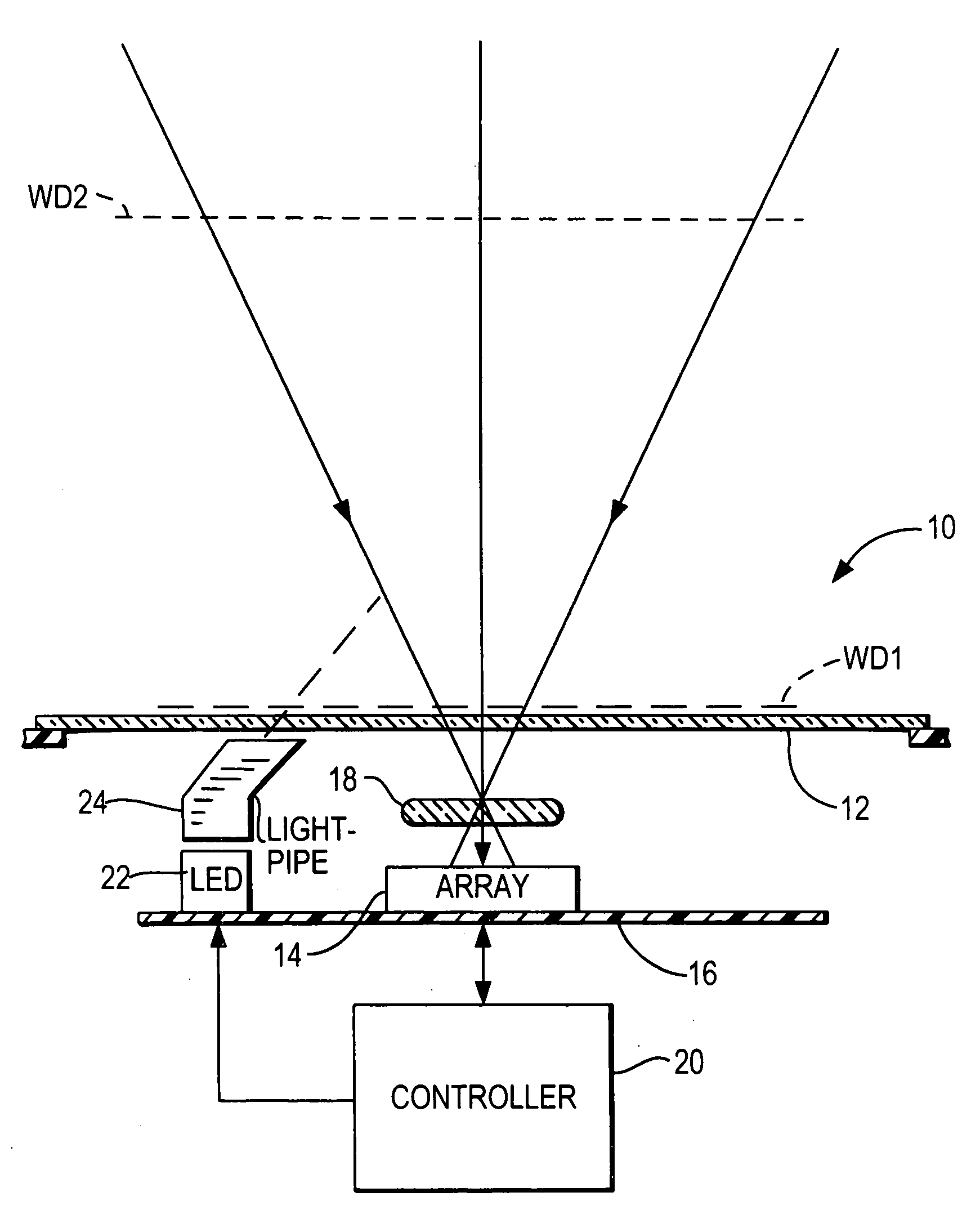
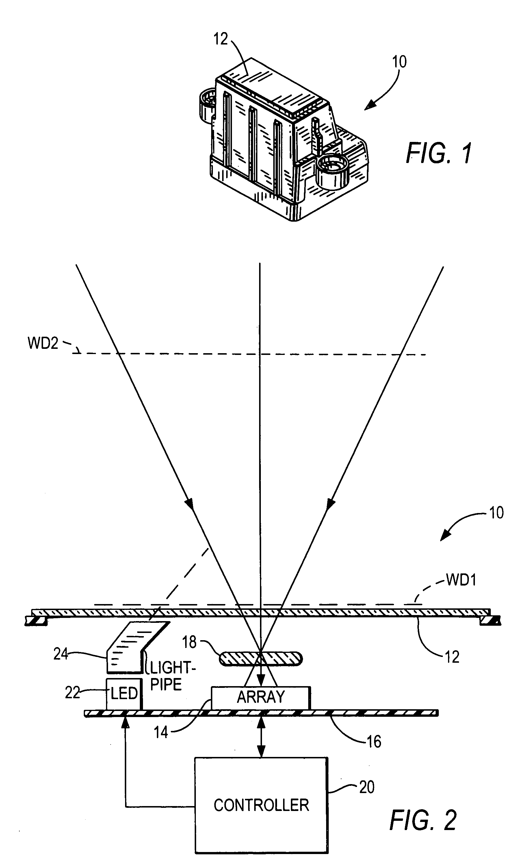
[0025]Reference numeral 10 in FIG. 1 generally identifies a data capture system or an electro-optical imaging reader for electro-optically reading indicia, such as bar code symbols, by capturing illumination and / or ambient light reflected or scattered from the symbols with an array of image sensors. In use, an operator presents each symbol to be read to a generally planar window 12. The reader 10 can be used as a stand-alone device, but has been especially designed herein to be portable, miniature, lightweight and inexpensive so that it can be readily installed as a subsidiary component in an apparatus operative for performing other functions.

[0026]As shown in FIG. 2, the imaging reader 10 includes an imager 14 supported on a printed circuit board 16 and a focusing collection or imaging lens 18 in front of the imager. The imager 14 is a solid-state device, for example, a CCD or a CMOS device and preferably has a linear array of addressable image sensors operative for sensing light p...


PUM


Abstract

An assembly for illuminating indicia includes a chassis, an illuminator for emitting illumination light, and a self-retaining lightpipe constituted of an optical material and non-adhesively mounted on the chassis with a snap action in an assembled position. The lightpipe is optically aligned with the illuminator in the assembled position, for optically guiding the illumination light from the illuminator to the indicia. The lightpipe has a textured exit surface, preferably with a predetermined scattering directionality, for scattering the illumination light exiting therefrom toward the indicia in a controlled manner to minimize specular reflection.

Description

BACKGROUND OF THE INVENTION[0001]Various moving beam and imaging electro-optical readers have previously been developed for reading both one- and two-dimensional bar code symbols appearing on a label, or on a surface of a target. The bar code symbol itself is a coded pattern of indicia. Generally, the readers electro-optically transform graphic indicia of the symbols into electrical signals, which are decoded into alphanumeric characters. The resulting characters describe the target and / or some characteristic of the target with which the symbol is associated. Such characters typically comprise input data to a data processing system for applications in point-of-sale processing, inventory control, article tracking and the like.[0002]The imaging reader includes a solid-state imager having a one- or two-dimensional array of cells or photosensors which correspond to image elements or pixels in a field of view of the imager. A collection lens captures either ambient light scattered from t...

Claims


Application Information

Patent Timeline
IPC IPC(8): F21V8/00G02B5/02
CPCG06K7/10732G02B5/021
Inventor WITTENBERG, CARLVINOGRADOV, IGOR
Owner SYMBOL TECH INC
Features
  • R&D
  • Intellectual Property
  • Life Sciences
  • Materials
  • Tech Scout
  • Unparalleled Data Quality
  • Higher Quality Content
  • 60% Fewer Hallucinations
Learn More