Axial compliance

Inactive Publication Date: 2009-03-05
SCROLL TECH
View PDF2 Cites 3 Cited by
  • Summary
  • Abstract
  • Description
  • Claims
  • Application Information

AI Technical Summary

Benefits of technology

[0007]In the disclosed embodiment of this invention, one of the two seals for defining the back pressure chamber is at a surface which is spaced away from the plane which receives the other seal. In this manne

Problems solved by technology

Thus, it will take a relatively longer time for the back pressure chamber to fill

Method used


Image

  • Axial compliance
  • Axial compliance
  • Axial compliance

Examples


embodiment 150

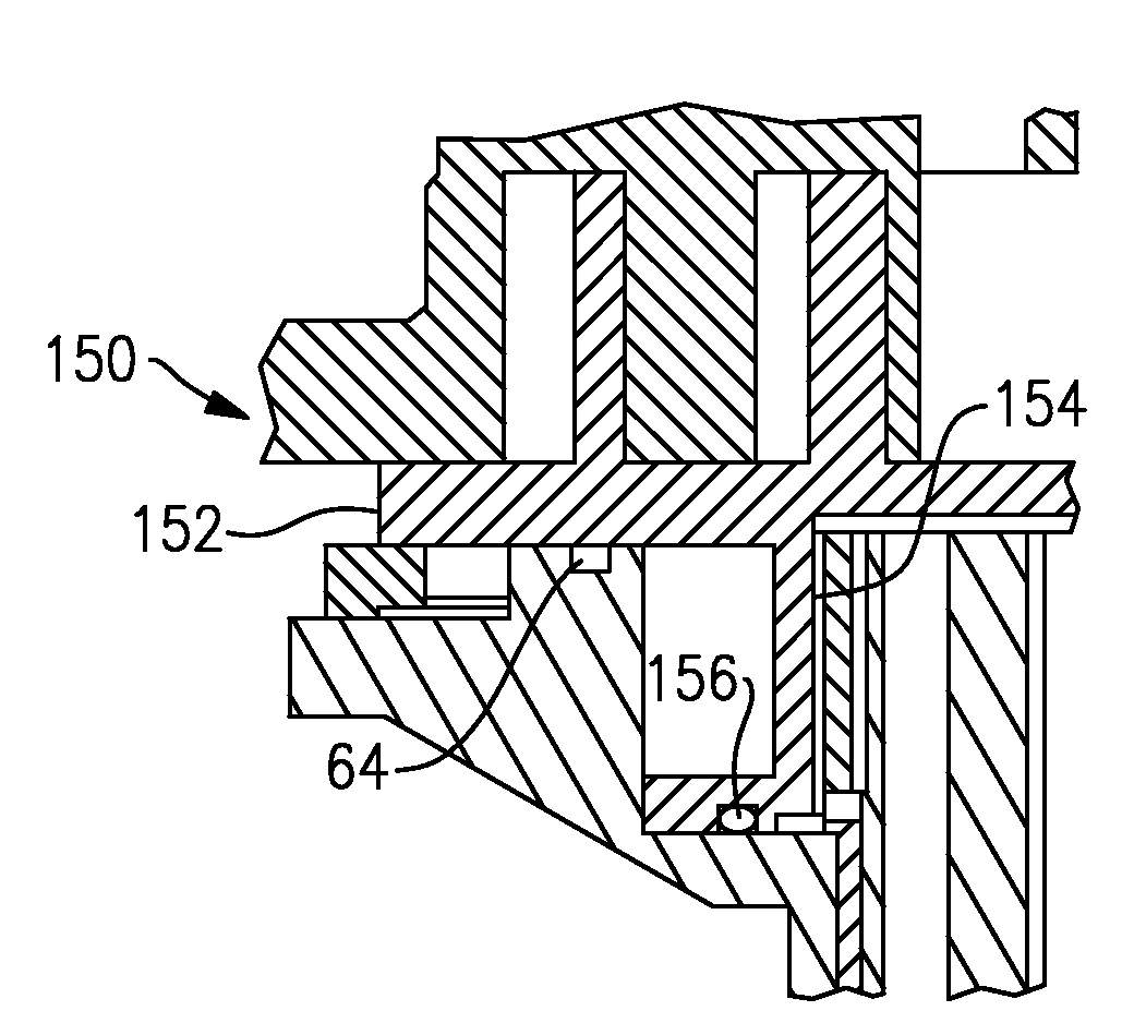
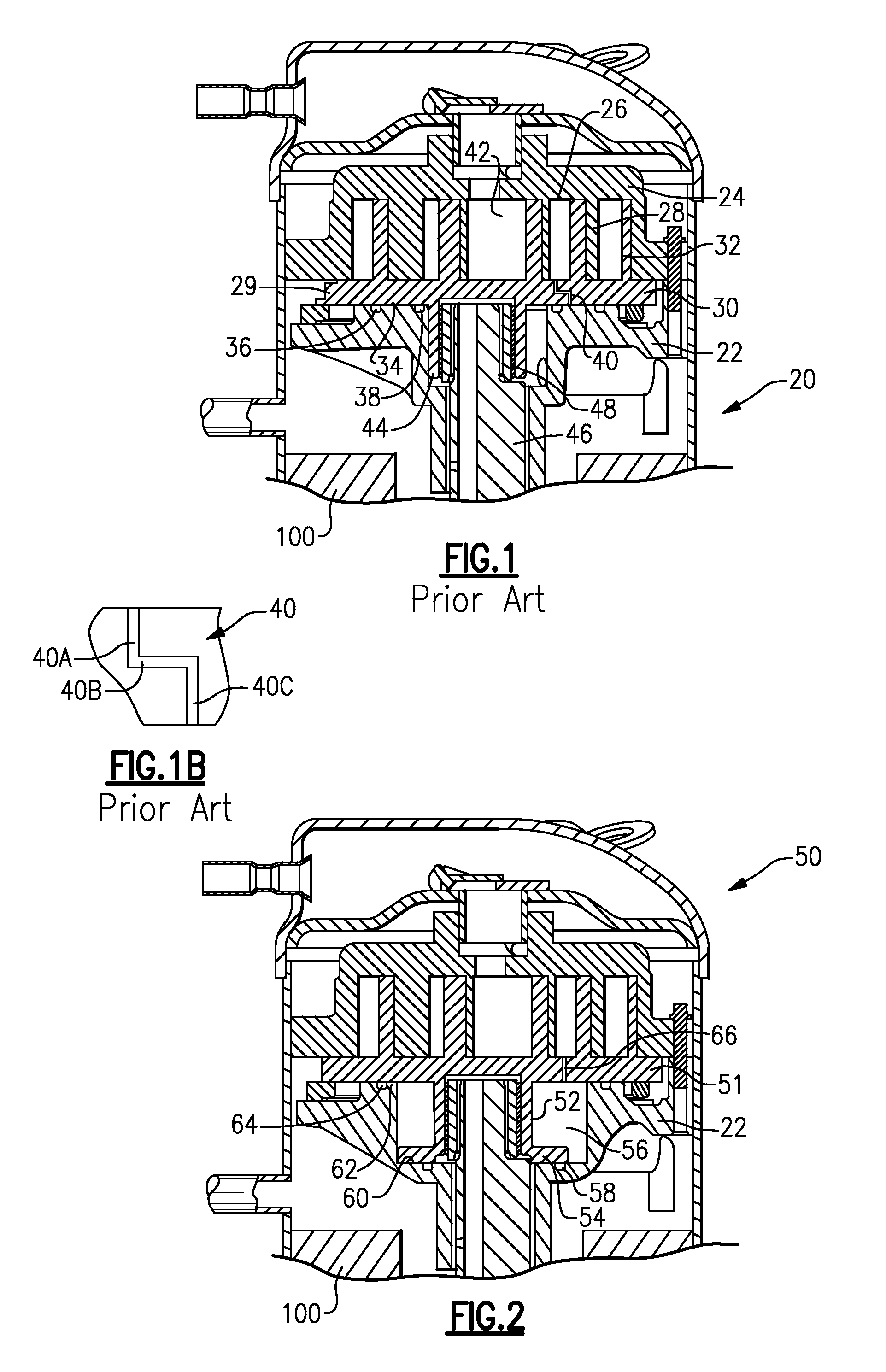
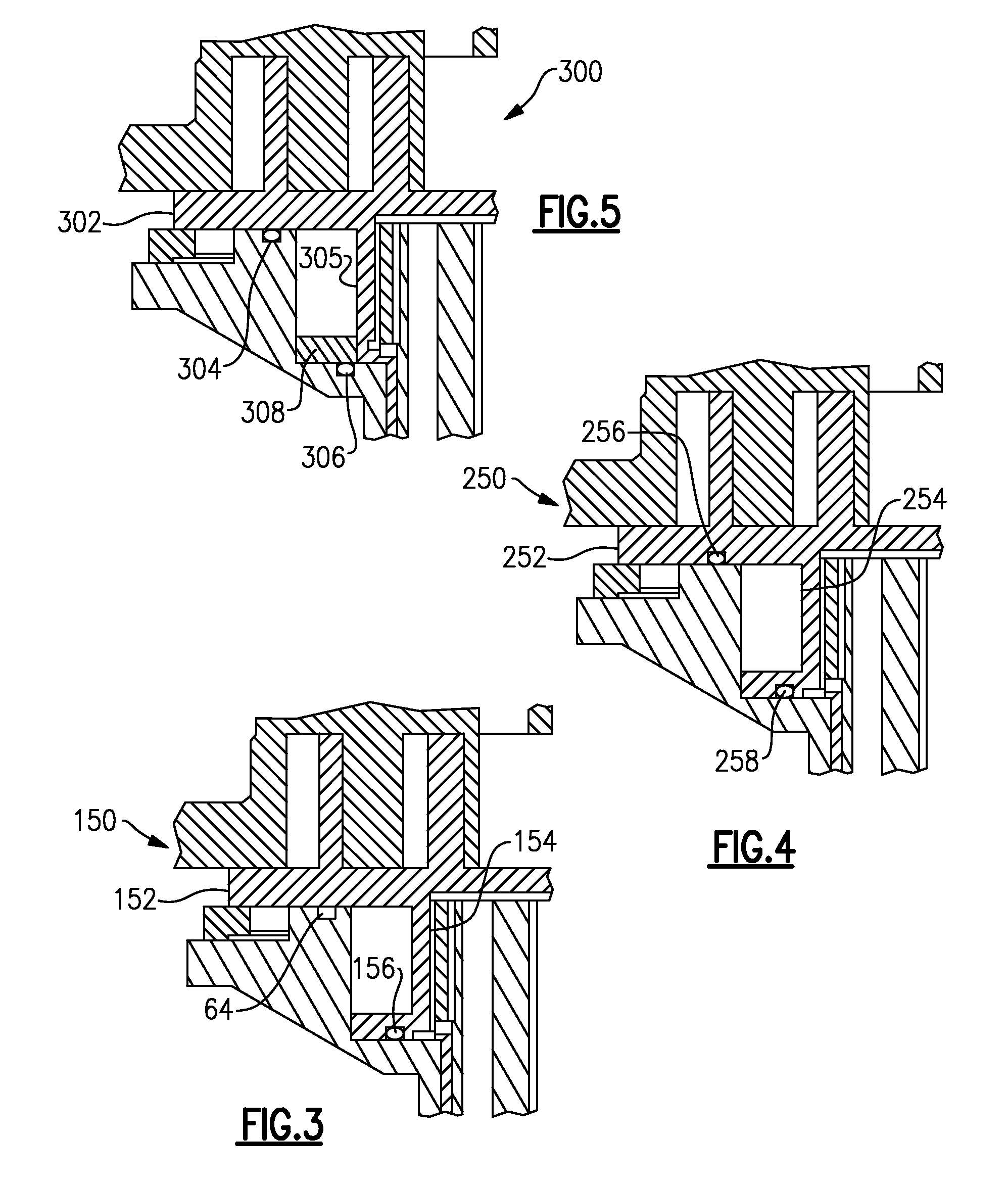
[0021]An embodiment 150 is shown in FIG. 3, wherein the radially inner seal 156 is in the hub 154 of the orbiting scroll 152. The radially outer seal 64 remains in the crankcase. Of course, the two seal locations could be reversed, with the radially outer seal in the orbiting scroll and the radially inner seal in the crankcase.

embodiment 250

[0022]FIG. 4 shows another embodiment 250 wherein the orbiting scroll 252 has the hub 254 receiving the radially inner seal 258. The base of the orbiting scroll 252 receives the radially outer seal 256.

embodiment 300

[0023]FIG. 5 shows another embodiment 300 wherein the orbiting scroll 302 includes a hub 305 with a separate member 308 that contacts the radially inner seal 306. The radially outer seal 304 sits in the crankcase in this embodiment. In this embodiment, the formation of the orbiting scroll is simplified in that the hub need not have the radially outwardly extending lowermost portion, but can instead receive a separate component to provide that function.


PUM


Abstract

A scroll compressor has its back pressure chamber defined by two seals. The two seals are on different planes. Locating the seals on two distinct planes allows a more direct connection for a tap through a compression chamber and the back pressure chamber. In addition, the volume of the back pressure chamber can be made significantly larger, reducing resistance at start-up of the scroll compressor.

Description

BACKGROUND OF THE INVENTION[0001]This application relates to a scroll compressor wherein a back pressure chamber is defined by inner and outer seals, with the seals on different planes. The formation of a tap for the back pressure chamber is simplified, and there is also less resistance at startup.[0002]Scroll compressors are becoming widely utilized in refrigerant compression applications. In a scroll compressor, a first scroll member has a base and a generally spiral wrap extending from the base. A second scroll member has a base and a generally spiral wrap extending from its base. The wraps interfit to define compression chambers, and one of the two scroll members is caused to orbit relative to the other. As the scroll member orbits, the size of the compression chambers decreases and an entrapped refrigerant is compressed.[0003]Generally, at least one of the two scroll members is allowed to move axially away from the other. As compression occurs a separating force is created whic...

Claims


Application Information

Patent Timeline
IPC IPC(8): F04C18/02
CPCF04C18/0215F04C18/0253F04C27/008F04C27/005F04C23/008F04C27/00
Inventor ZAMUDIO, CARLOS
Owner SCROLL TECH
Why Eureka
Try Eureka