Hollow turbomachine blade

a technology of turbomachine blades and hollow blades, which is applied in the direction of liquid fuel engines, marine propulsion, and vessel construction, etc., can solve the problems of limiting the amount of gas, weakening the suction rim, and affecting the efficiency of the machine, so as to achieve the effect of simple manufacturing

Active Publication Date: 2009-05-12
SN DETUDE & DE CONSTR DE MOTEURS DAVIATION S N E C M A
View PDF8 Cites 20 Cited by
  • Summary
  • Abstract
  • Description
  • Claims
  • Application Information

AI Technical Summary

Benefits of technology

[0009]An object of the invention is to provide a hollow blade for a turbomachine that is simple to manufacture and in which the end rim(s) is / are well cooled.
[0012]This disposition allows the cooling air escaping from the channels to run along the wall of the rim and thus form a protective air film on said wall, protecting the rim from the hot gases and cooling it.
[0013]In addition, this inclination of the side wall of the rim makes it easier to drill the cooling channels: it is easy to drill these channels even in a vertical direction, since the space over the junction zone between the end wall and the side wall is sufficiently unencumbered to allow a laser beam or a tool (e.g. an electrode) to pass. Conversely, it can be observed that drilling a channel at the base of a rim side wall forming an acute angle or a right angle with the end wall is an operation that is lengthy and difficult since care needs to be taken to avoid damaging the side wall and to avoid piercing the channel too far away from said wall.

Problems solved by technology

Furthermore, the rims 9 and 10 serve to optimize the clearance J between the free end of the blade 3 and the casing 16, and thus limit the amount of gas that can pass from the pressure side to the suction side, thereby generating aerodynamic losses that are harmful to the efficiency of the machine.
However, the absence of a pressure rim 9 makes it necessary to improve the cooling of the suction rim 10, since it is no longer protected from hot gas by the pressure rim 9.
The main drawback of those notches are that they weaken the suction rim, in particular at its top end, and they confine the cool air so that the wall portions that are situated between the notches are cooled not at all (or very poorly).
In addition, depending on the shapes of the notches, it can be difficult to drill the cooling channels, and that operation can require specific equipment.

Method used


Image

  • Hollow turbomachine blade
  • Hollow turbomachine blade
  • Hollow turbomachine blade

Examples


Embodiment Construction

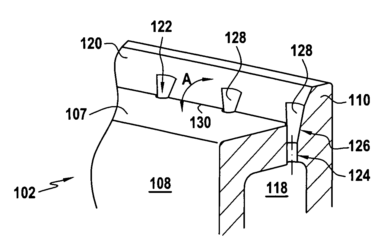
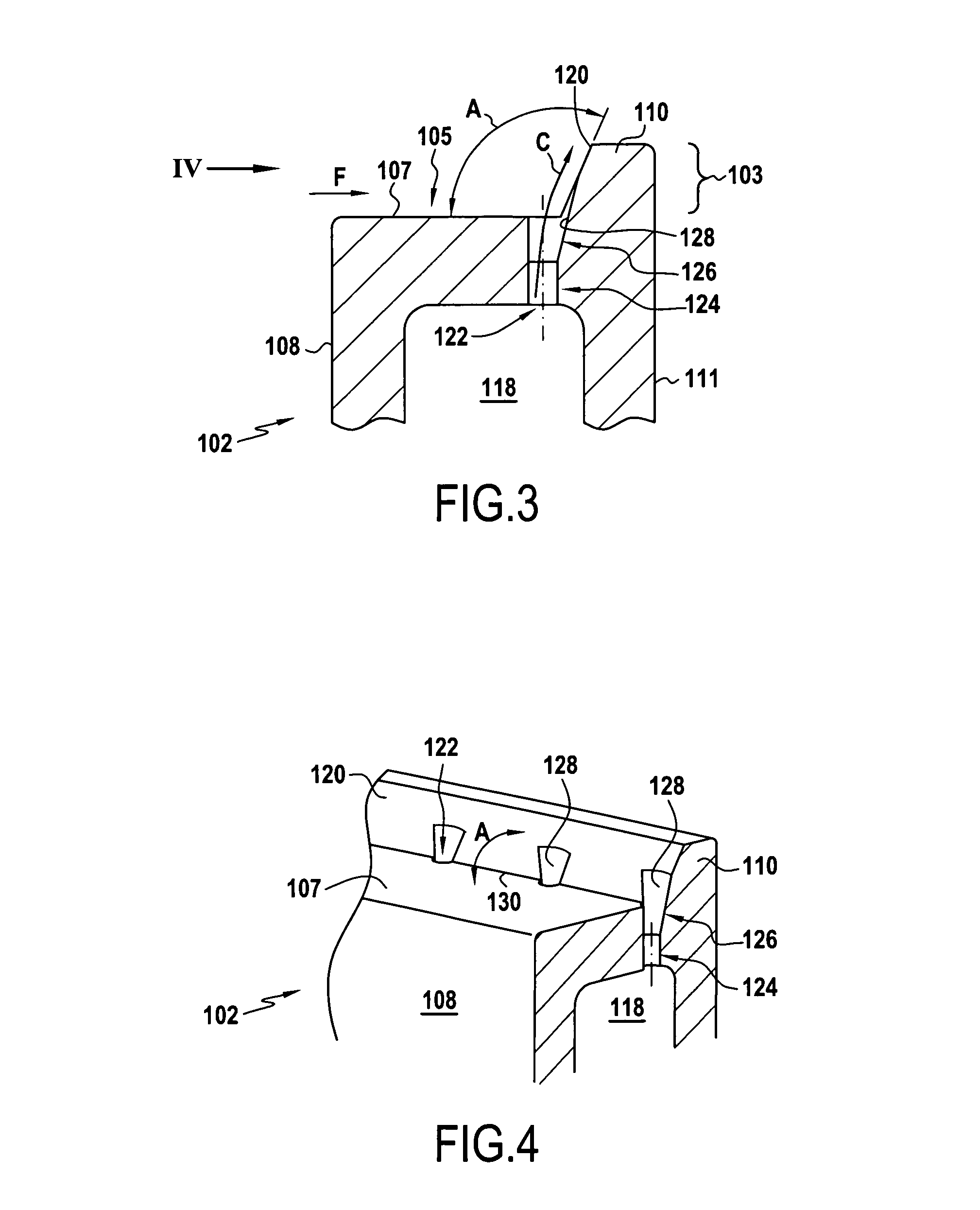
[0020]With reference to FIGS. 3 and 4, there follows a description of an embodiment of a blade 102 of the invention. Portions of the blade 102 that are analogous to portions of the blade 2 shown in FIGS. 1 and 2 are given the same reference numbers plus 100.

[0021]In the example of FIGS. 3 and 4, the free end 103 of the blade 102 presents a suction rim 110 in the region that is shown, but it does not present a pressure rim.

[0022]The side wall 120 of the suction rim co-operates with the end wall 107 to define the open cavity 105. Because there is no pressure rim, the side wall 120 is struck by the hot gas flowing through the turbine and driving the blades 102. Relative to the blade, the hot gas flows in the direction of arrow F. The side wall 120 is thus subjected to very high temperatures and needs to be cooled effectively.

[0023]For this purpose, cooling channels 122 connect the internal cooling passage 118 of the blade 102 to the cavity 105 and open out to the base of the rim 110 at...


PUM


Abstract

A hollow turbomachine blade including an internal cooling passage, an open cavity situated at the free end of the blade and defined by an end wall and the side wall of at least one rim which extends between the leading edge and the trailing edge of the blade, and at least one cooling channel connecting said internal cooling passage to said open cavity, said cooling channel opening out at the base of the rim and the wall of the rim forming an angle relative to said end wall that is obtuse, being strictly greater than 90°. An indentation may be formed in the wall of the rim at the outlet from said cooling channel. Said blade advantageously does not include a pressure rim.

Description

[0001]The invention relates to a hollow turbomachine blade, and more particularly it can relate to a hollow blade of the type for a high-pressure gas turbine rotor in a turbojet.BACKGROUND OF THE INVENTION[0002]As shown in FIGS. 1 and 2, it is known to provide an open cavity 5 or “bathtub” at the free end 3 of a hollow blade 2, the cavity being defined by an end wall 7 that extends over the entire end of the blade, and by side walls in the form of two rims 9 and 10 that extend between the leading edge 12 and the trailing edge 14 of the blade, one of the two rims 9 extending the pressure side wall 8 of the blade while the other rim extends the suction side wall 11 of the blade. These rims are referred to herein as the pressure rim and the suction rim.[0003]The rubbing surfaces between the free end 3 of each blade and the annular surface of the turbine casing 16 that surrounds the blades, as shown in FIG. 2, are thus restricted to the rims 9 and 10 so as to protect the body of the bla...

Claims


Application Information

Patent Timeline
Patent Type & Authority Patents(United States)
IPC IPC(8): F01D5/18
CPCF01D5/20Y02T50/673Y02T50/60
Inventor BOURY, JACQUES AUGUSTE AMEDEBONNEAU, DAMIENFACHAT, THIERRY
Owner SN DETUDE & DE CONSTR DE MOTEURS DAVIATION S N E C M A
Why Eureka
Try Eureka