
Metal plate drilling device

A drilling device and metal plate technology, applied in positioning devices, metal processing, boring/drilling, etc., can solve the problems of inconvenient drilling, waste of raw materials, and inability to accurately control the depth of metal plates, so as to avoid hard contact , the effect of improving the service life

Inactive Publication Date: 2018-07-17
陈灵燕
View PDF0 Cites 21 Cited by
  • Summary
  • Abstract
  • Description
  • Claims
  • Application Information

AI Technical Summary

Problems solved by technology

[0005] Aiming at the deficiencies of the prior art, the present invention provides a metal plate drilling device, which has the advantages of being convenient to precisely control the drilling depth and fixing the thinner metal plate, and solves the problem of the common drilling device in the metal plate. When drilling, the depth of the metal plate cannot be accurately controlled, so that the quality of the metal plate drilling cannot meet the engineering requirements, resulting in waste of raw materials and reducing the processing efficiency of the metal plate, and common drilling devices are not suitable for thinner metal When the plate is fixed, the thinner metal plate is easy to bulge after being squeezed, which is inconvenient for the operator to drill holes and affects the drilling efficiency of the metal plate

Method used


Image

  • Metal plate drilling device
  • Metal plate drilling device
  • Metal plate drilling device

Examples


Embodiment Construction

[0034] The following will clearly and completely describe the technical solutions in the embodiments of the present invention with reference to the accompanying drawings in the embodiments of the present invention. Obviously, the described embodiments are only some, not all, embodiments of the present invention. Based on the embodiments of the present invention, all other embodiments obtained by persons of ordinary skill in the art without making creative efforts belong to the protection scope of the present invention.

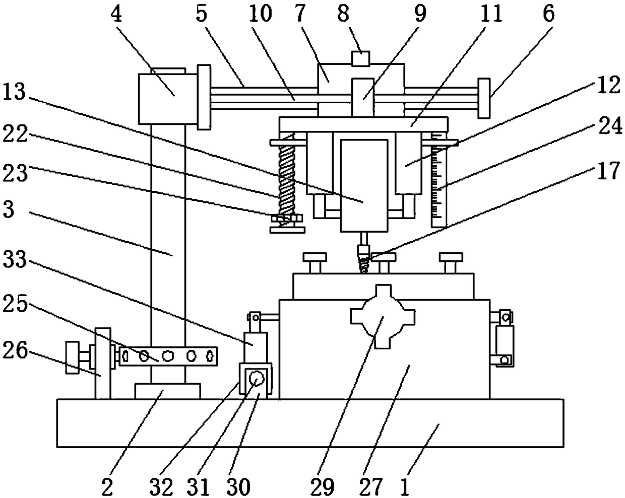
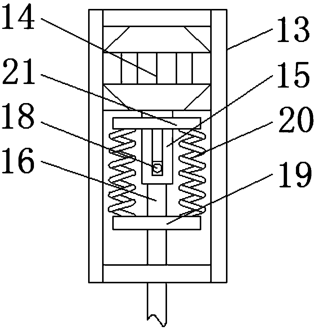
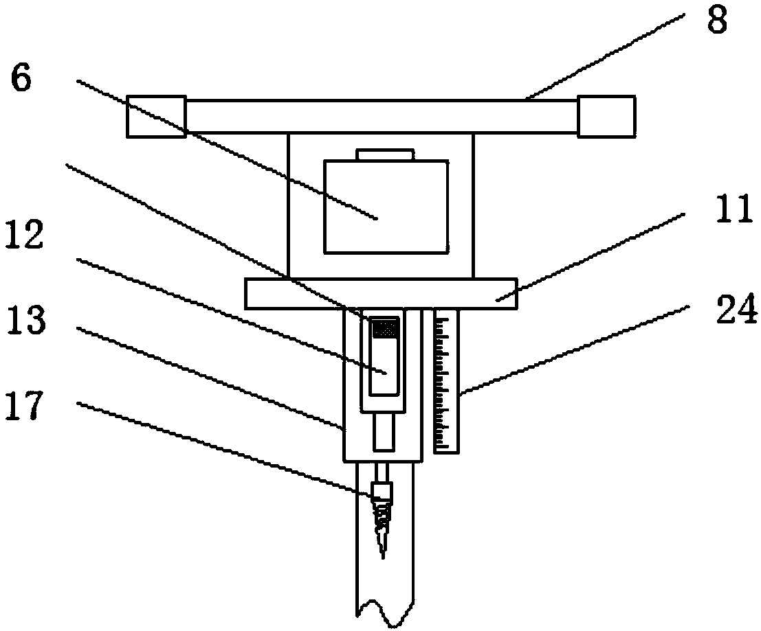
[0035] see Figure 1-11 , a metal plate drilling device, comprising a base 1, an end face bearing 2 is fixedly installed on one side of the top of the base 1, a support column 3 is fixedly set in the middle of the end face bearing 2, and a rotating block 4 is fixedly set on the top end of the support column 3, The side of the rotating block 4 is fixedly connected to the sliding bar 5, and the end of the sliding bar 5 away from the rotating block is fixedly con...


PUM


Abstract

The invention relates to the field of drilling equipment, and discloses a metal plate drilling device. The metal plate drilling device comprises a base. An end face bearing is fixedly arranged on oneside of the top of the base. A supporting column is fixedly sleeved with the middle portion of the end face bearing. The top end of the supporting column is fixedly sleeved with a rotation block. A sliding rod is fixedly connected to the side face of the rotation block. The end, away from the rotation block, of the sliding rod is fixedly connected with a limiting baffle. According to the metal plate drilling device, a positioning nut rotates on a threaded rod, and the deepest punching position is determined in cooperation with the positions of a right side marker post and a dividing ruler. During punching, only a moving pipe needs to be downwards moved, a drill bit is driven to move downwards to conduct drilling till a left side marker post makes contact with the positioning nut, then drilling is conducted to the deepest position, accordingly, the situation that the metal plate depth cannot be accurately controlled, the metal plate drilling quality cannot meet the project requirement,consequently, raw materials are wasted, and the metal plate machining efficiency is reduced is avoided.

Description

technical field [0001] The invention relates to the field of drilling equipment, in particular to a metal plate drilling device. Background technique [0002] Drilling device refers to the general term for equipment used to process holes on solid materials. Common drilling devices include electric drills, drilling machines, and drilling devices are widely used. In the construction industry, they are suitable for building beams, plates, columns, Wall reinforcement, decoration, wall installation, installation of brackets, railings, billboards, outdoor units of air conditioners, guide rails, satellite receiver elevators, steel structure workshops, etc. [0003] However, the common drilling device cannot accurately control the depth of the metal plate when drilling the metal plate, so that the quality of the metal plate drilling cannot meet the engineering requirements, resulting in waste of raw materials and reducing the processing efficiency of the metal plate. Moreover, when...

Claims


Application Information

Patent Timeline
Patent Type & Authority Applications(China)
IPC IPC(8): B23B41/02B23Q3/06
CPCB23B41/02B23B2260/0482B23Q3/062
Inventor 陈灵燕
Owner 陈灵燕
Learn More