Eureka AIR delivers breakthrough ideas for toughest innovation challenges, trusted by R&D personnel around the world.

Formal Verification of Graphical Programs

a verification system and graphical program technology, applied in the field of graphical programming, can solve the problems of user programming skills and ability to interact with the computer system often becoming a limiting factor in the achievement of optimal utilization of the computer system, complex task of programming a computer system to model or implement a process, and user often not fully proficient in techniques

Inactive Publication Date: 2009-03-05
NATIONAL INSTRUMENTS
View PDF17 Cites 21 Cited by
  • Summary
  • Abstract
  • Description
  • Claims
  • Application Information

AI Technical Summary

Benefits of technology

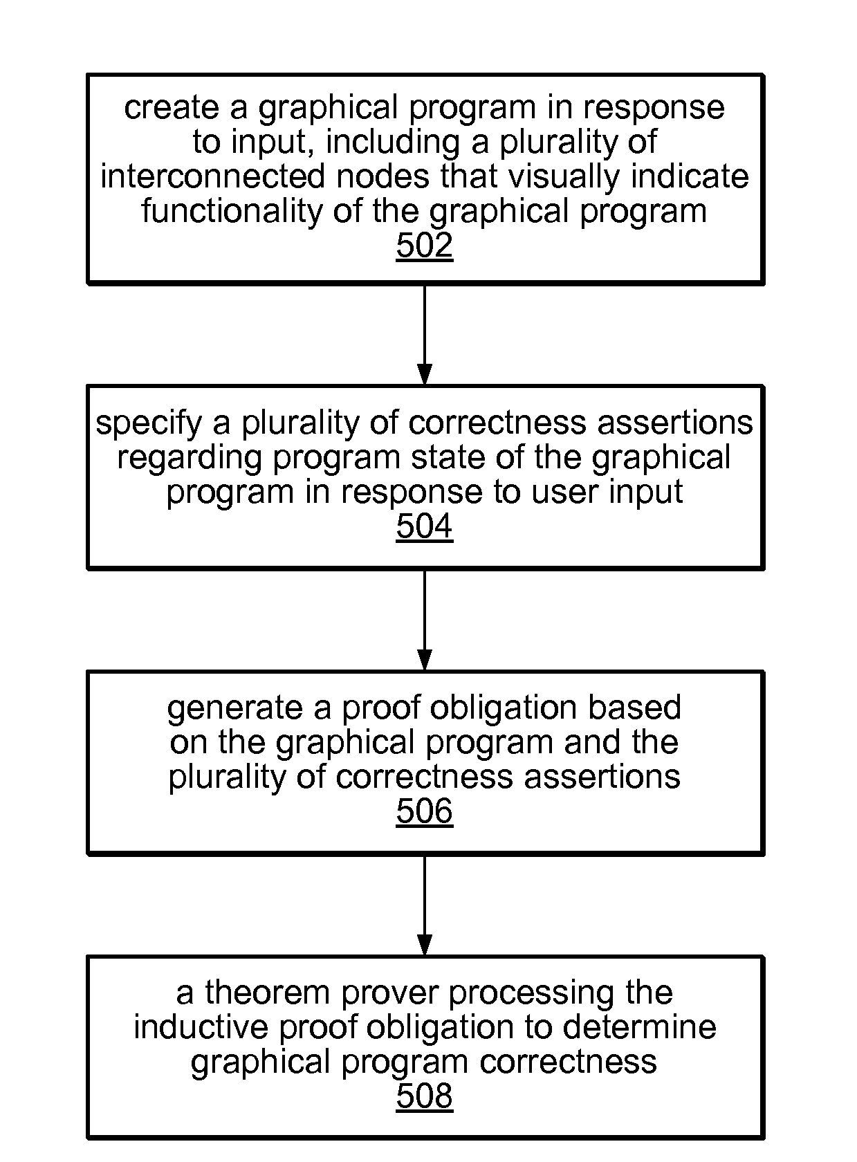
[0027]In some embodiments, a theorem prover may process the proof obligation to determine program correctness, i.e., whether the graphical program is correct or not, e.g., whether the program generates the correct result, and/or operates in a correct manner. Said another way, the theorem prover may determine if the graphical program is consistent with the one or more correctness assertions. In some embodiments, the theorem prover processing the proof obligation to determine whether the graphical program is correct may include the theorem prover attempting to determine a proof of the correctness of the graphical program.
[0028]If the theorem prover fails to prove program correctness, the theorem prover may provide information indicating where the proof of program correctness failed. For example, the information indicating where the proof of program correctness failed may include information indicating that the proof of program correctness failed at a location in one or more of: the proof obligation, or the graphical program. In other words, feedback may be provided to the user indicating or hinting at where problems with the program correctness are. In some embodiments, information indicating possible avenues for correcting the graphical program may be provided. The user may then modify the graphical program and/or the correctness

Problems solved by technology

When traditional text-based programming environments are used, the user's programming skills and ability to interact with the computer system often become a limiting factor in the achievement of optimal utilization of the computer system.
There are numerous subtle complexities which a user must master before he can efficiently program a computer system in a text-based environment.
The task of programming a computer system to model or implement a process often is further complicated by the fact that a sequence of mathematical formulas, steps or other procedures customarily used to conceptually model a process often does not closely correspond to the traditional text-based programming techniques used to program a computer system to model such a process.
Since a user often is not fully proficient in techniques for programming a computer system in a text-based environment to implement his solution, the efficiency with which the computer system can be utilized often is reduced.
However, as programs have become increasingly complex, it has become increasingly difficult to perform such verification.
However, due in large part to the generally overwhelming magnitude of the state space for any but the simplest of programs, such software testing is neither exhaustive nor particularly reliable.
For example, it has been noted that the state space of possible execution traces in most programs has more possible paths than there are electrons in the universe, and so exhaustive testing to cover this space is not feasible, or even possible.
Thus, software testing is not exhaustive, and cannot generally provide confirmation that applications are correct or predictable.
While formal proof-based program verification has been studied for some time in academic contexts, such systems are typically arcane and difficult to use, and thus have not been available or useful for general use.
Moreover, such formal program verification systems have not been developed for graphical programming systems, such as LabVIEW.

Method used


Image

  • Formal Verification of Graphical Programs
  • Formal Verification of Graphical Programs
  • Formal Verification of Graphical Programs

Examples


Embodiment Construction

Incorporation by Reference:

[0042]The following references are hereby incorporated by reference in their entirety as though fully and completely set forth herein:

[0043]U.S. Provisional Application 60 / 821,679, titled “Formal Verification of Graphical Programs”, filed Aug. 7, 2006.

[0044]U.S. Pat. No. 4,914,568 titled “Graphical System for Modeling a Process and Associated Method,” issued on Apr. 3, 1990.

[0045]U.S. Pat. No. 5,481,741 titled “Method and Apparatus for Providing Attribute Nodes in a Graphical Data Flow Environment”.

[0046]U.S. Pat. No. 6,173,438 titled “Embedded Graphical Programming System” filed Aug. 18, 1997.

[0047]U.S. Pat. No. 6,219,628 titled “System and Method for Configuring an Instrument to Perform Measurement Functions Utilizing Conversion of Graphical Programs into Hardware Implementations,” filed Aug. 18, 1997.

[0048]U.S. Patent Application Publication No. 20010020291 (Ser. No. 09 / 745,023) titled “System and Method for Programmatically Generating a Graphical Progr...


PUM


Abstract

System and method for formal verification of a graphical program. A graphical program comprising a plurality of interconnected nodes is created in response to input. One or more correctness assertions regarding program state of the graphical program are specified in response to user input, and a proof obligation generated based on the graphical program and the correctness assertions, which is usable by a theorem prover to determine correctness of the graphical program. The proof obligation may be generated by compiling the graphical program to generate an object-level diagram, parsing the correctness assertions to generate an intermediate logical form of the one or more correctness assertions, and analyzing the object-level diagram, the intermediate logical form, and / or semantics of the graphical programming language in which the graphical program is written to generate the proof obligation. A theorem prover may then process the proof obligation to determine whether the graphical program is correct.

Description

PRIORITY DATA[0001]This application claims benefit of priority to U.S. Provisional Application 60 / 821,679, titled “Formal Verification of Graphical Programs”, filed Aug. 7, 2006, and whose inventors were Jacob Kornerup and Grant O. Passmore.FIELD OF THE INVENTION[0002]The present invention relates to the field of graphical programming, and more particularly to a system and method for formal verification of graphical programs.DESCRIPTION OF THE RELATED ART[0003]Traditionally, high level text-based programming languages have been used by programmers in writing application programs. Many different high level text-based programming languages exist, including BASIC, C, C++, Java, FORTRAN, Pascal, COBOL, ADA, APL, etc. Programs written in these high level text-based languages are translated to the machine language level by translators known as compilers or interpreters. The high level text-based programming languages in this level, as well as the assembly language level, are referred to h...

Claims


Application Information

Patent Timeline
IPC IPC(8): G06F9/44
CPCG06F11/3608G06F8/34
Inventor KORNERUP, JACOBPASSMORE, GRANT O.
Owner NATIONAL INSTRUMENTS
Why Eureka
Eureka Blog
Learn More